
Deep well type atmospheric pressure heat supply nuclear reactor

A technology of nuclear reactors and deep wells, applied in the field of nuclear reactors, can solve the problems of deepening burnup, low safety reactor years, and insufficient use of fuel components, so as to achieve the effect of shielding protection and improving safety margins

Inactive Publication Date: 2016-03-02
启迪新核(北京)能源科技有限公司
View PDF12 Cites 4 Cited by
  • Summary
  • Abstract
  • Description
  • Claims
  • Application Information

AI Technical Summary

Problems solved by technology

[0008] Existing technical problems: it is to release nuclear energy by nuclear fission under high pressure and high temperature conditions. Although after more than 50 years of development and continuous progress in R&D, design, experiment, construction and operation, the settings around the core, containment and pressure vessel are becoming more and more There are many safety barriers, and the probability of a safe reactor year is still low. Many domestic CPR1000, second-generation plus are all second-generation and a half-level nuclear power plants; American AP1000, French EPR and China Hualong One: mainly to increase core waste heat The passive exhaust system is a third-generation nuclear power plant, and there is no demonstration reactor yet
These spent fuel assemblies have not used the upper limit of burnup, and have not fully utilized the potential of fuel assemblies to further deepen burnup (is there a problem with existing technology?) It is not a problem with existing technology, but with the power of nuclear power plant reactors and operating conditions

Method used


Image

  • Deep well type atmospheric pressure heat supply nuclear reactor

Examples


Embodiment Construction

[0029] In conjunction with the accompanying drawings, the structure of a deep well type atmospheric heating nuclear reactor of the present invention is further described: this embodiment is only used to illustrate the present invention and is not intended to limit the scope of the present invention. Modifications in form all fall within the scope defined by the appended claims of this application.

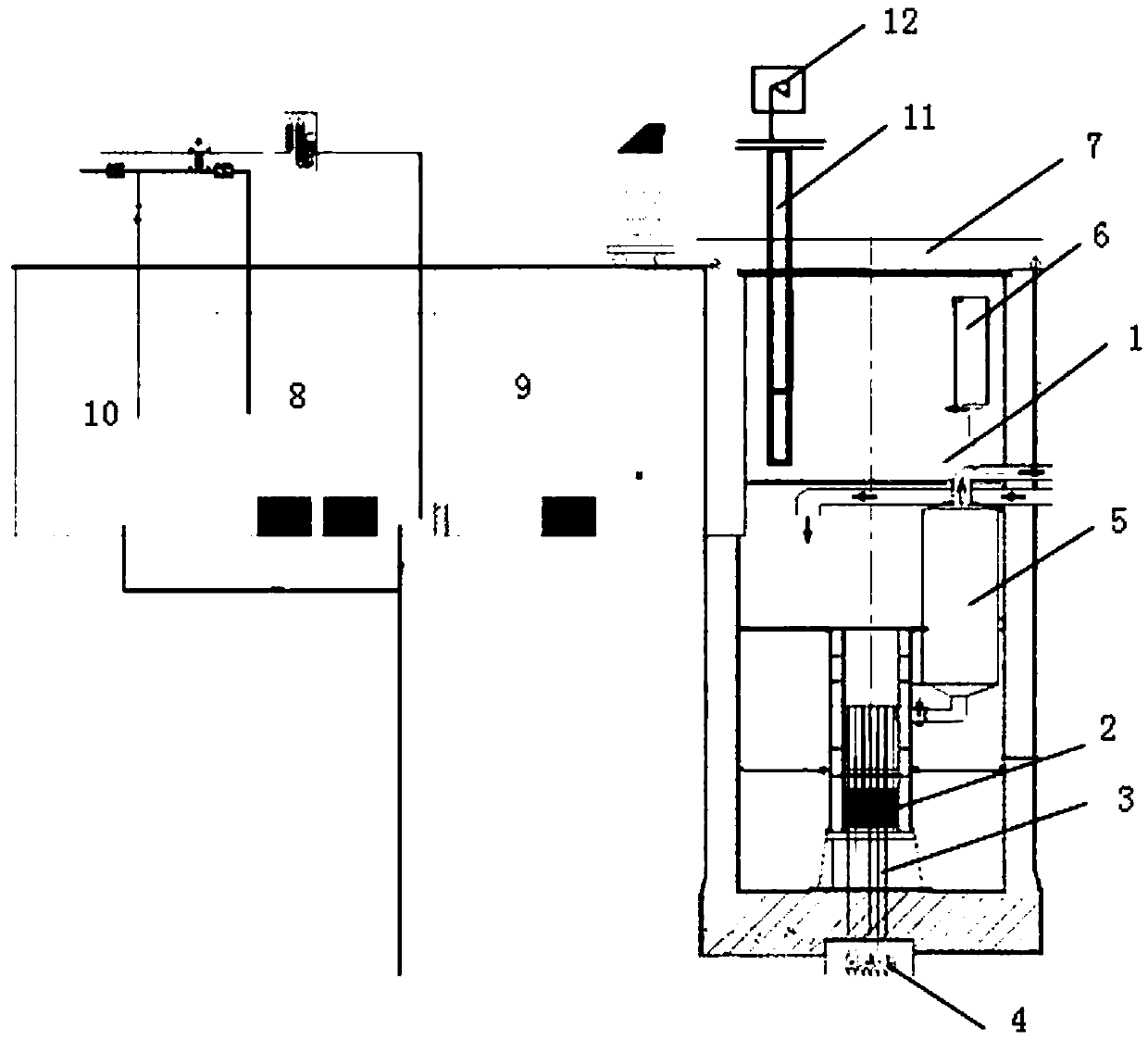
[0030] Such as figure 1 As shown, a deep well type atmospheric heating nuclear reactor includes a deep well 1, a core 2 placed at the bottom of the well, a control rod 3, a control rod drive mechanism 4, a safety pool, n radiation attenuation tubes 5, and n Inertial water tank 6, core waste heat removal system and movable manhole cover 7, the radiation attenuation cylinder 5 is arranged around the core 2, the radiation attenuation cylinder 5 is connected to the inertial water tank 6, n≥2; wherein,

[0031] The side wall and the bottom of the deep well include concrete lining the i...


PUM


Abstract

The invention provides a deep well type atmospheric pressure heat supply nuclear reactor comprising a deep well which is buried in the ground, a reactor core which is arranged at the bottom part of the well, a control rod and a control rod driving mechanism. The deep well type atmospheric pressure heat supply nuclear reactor is characterized by further comprising an underground safety pool, an attenuation box, an inertial water tank, a reactor core residual heat removal system and a removable well cover. A radiation attenuation cylinder is connected with the inertial water tank. Water is fully filled in the underground deep well. The deep well type atmospheric pressure heat supply nuclear reactor has extremely low operation pressure, and operation temperature of the reactor is greatly reduced by the requirement of low temperature heat supply. The underground atmospheric pressure low temperature deep well type reactor has no pressure vessel, containment vessel or safety injection and offsite emergency system so that the nuclear reactor is safest and simplest in structure and meets the heat supply requirement through nuclear energy. Meanwhile, the deep well and a spent fuel pool are connected with high-capacity water, radioactivity of radioactive substance can be quite effectively shielded by purified water, safety of operators around the heat well can be guaranteed, and 90 days of nuclear reactor safety can still be maintained under the condition of the biggest natural and man-made disasters including failure of all equipment of the non-dynamic reactor core residual heat removal system without intervention.

Description

technical field [0001] The invention relates to the field of nuclear reactors, in particular to a low-temperature and atmospheric-pressure heating nuclear reactor in a deep well. Background technique [0002] Deep-well atmospheric pressure heating nuclear reactor is a low-temperature heating reactor. This kind of reactor works at a lower temperature and directly supplies the heat energy generated by nuclear fission to low-temperature users. It has a simple structure and is easy to build, but it requires high safety and reliability. At present, the low-temperature nuclear heating reactors designed and built at home and abroad use deep water pools to increase the temperature of the core outlet water by hydrostatic pressure, so as to achieve the purpose of increasing the temperature of the water supply. [0003] The heat transfer system of the primary circuit of the pressurized water reactor nuclear power plant refers to the fission heat of the core fuel in the pressure shell ...

Claims


Application Information

Patent Timeline
Patent Type & Authority Applications(China)
IPC IPC(8): G21D9/00G21C11/02
CPCY02E30/00Y02E30/30
Inventor 田力徐刚郭夏王洪林田笑梅贺宪清
Owner 启迪新核(北京)能源科技有限公司
Learn More