
window regulator motor

A technology for lifters and car windows, which is applied in the direction of electrical components, electromechanical devices, electric components, etc., can solve the problems of motor rotor rust, poor dust-proof effect, motor short-circuit failure, etc., and achieve the effect of preventing water and dust from entering

Active Publication Date: 2017-11-24
宁波世通汽车零部件有限公司
View PDF5 Cites 0 Cited by
  • Summary
  • Abstract
  • Description
  • Claims
  • Application Information

AI Technical Summary

Problems solved by technology

However, when the water flow is large, or the motor is soaked in water, the water can still flow into the cavity of the motor casing through the vent pipe of the end cover, so that the rotor of the motor is rusted or the motor is short-circuited and fails.
In addition, after the motor shell cavity is directly connected with the outside air, the dust in the air can fly into the motor shell cavity, so the dustproof effect is very poor. After a period of time, the performance of the motor will decline, and the motor will even produce abnormal noise

Method used


Image

  • window regulator motor
  • window regulator motor
  • window regulator motor

Examples


Embodiment Construction

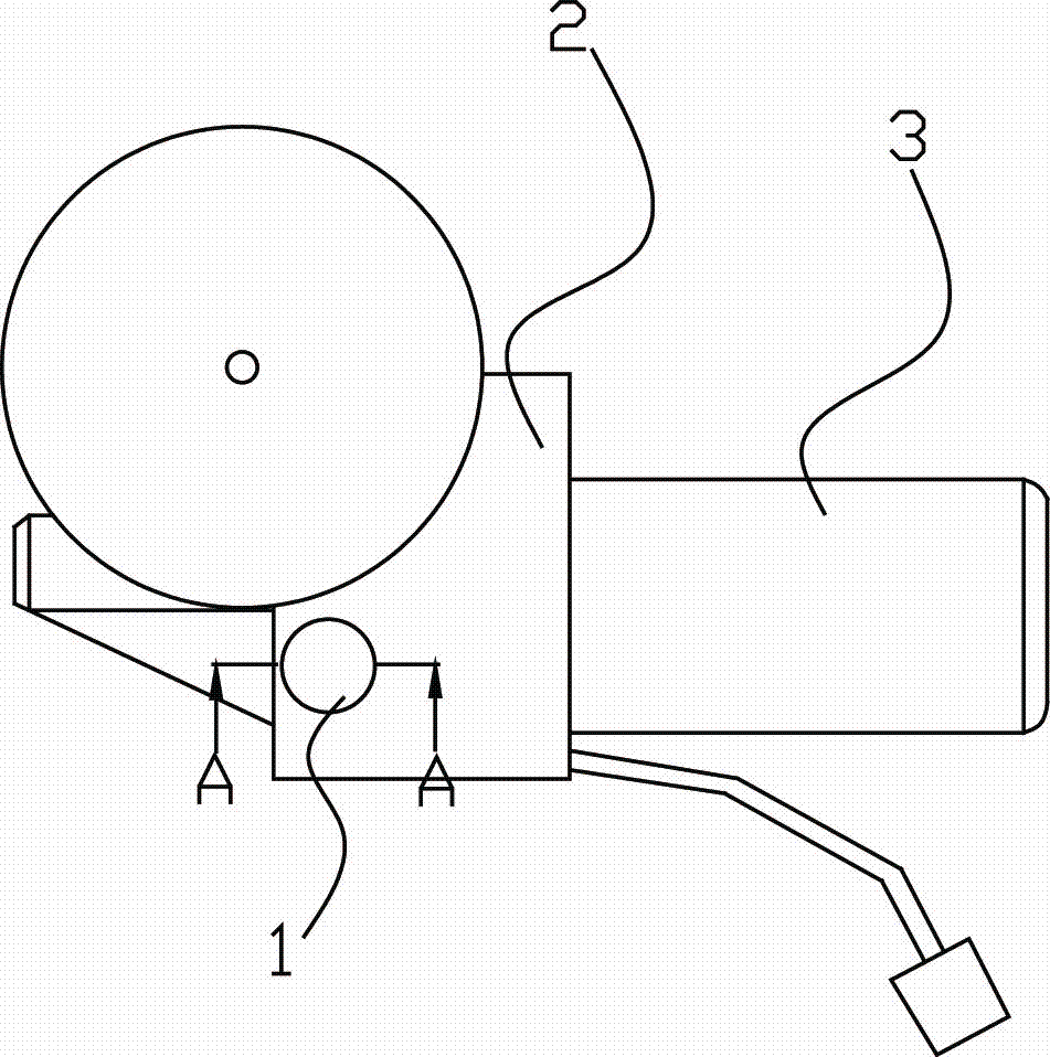
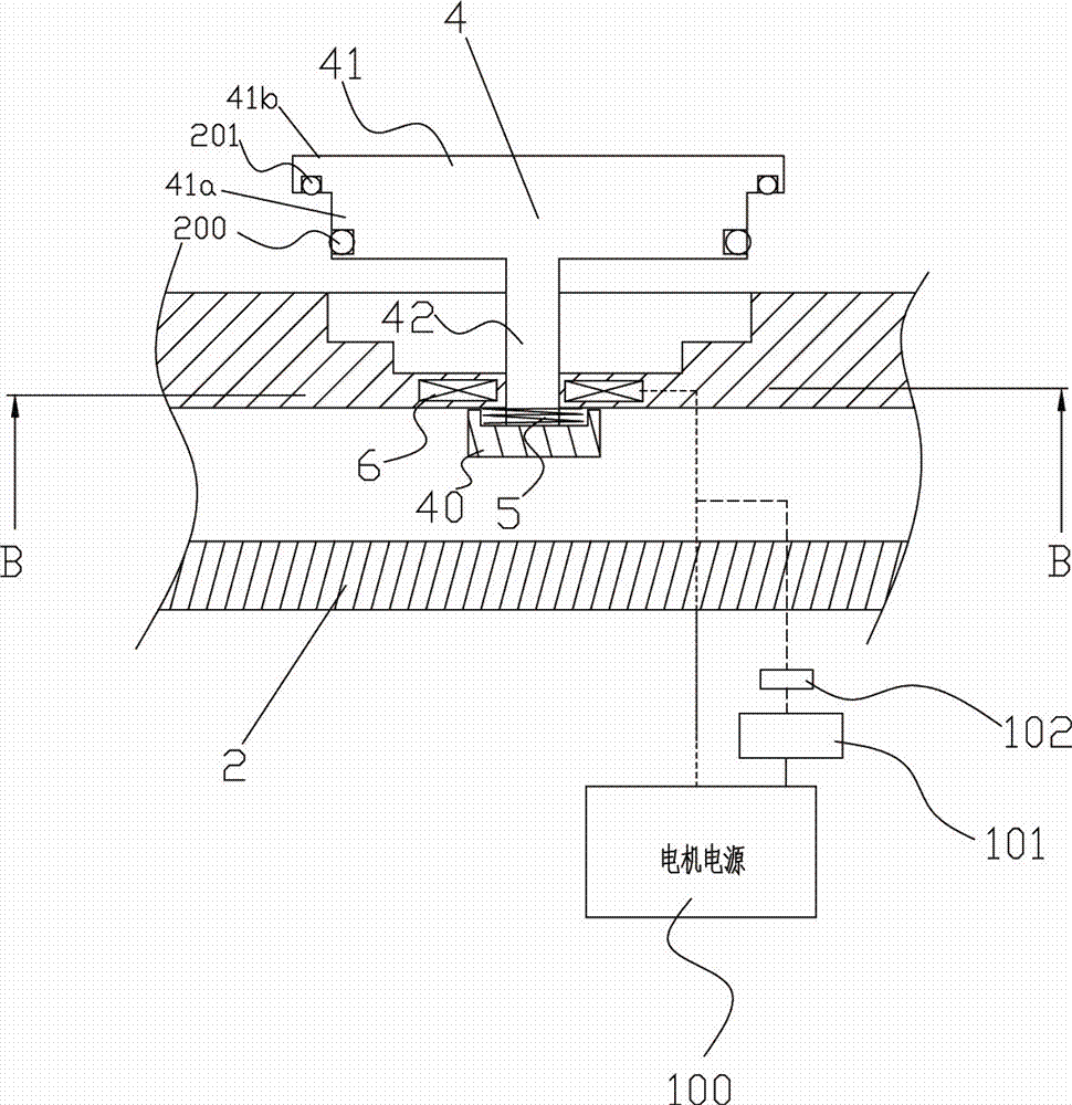
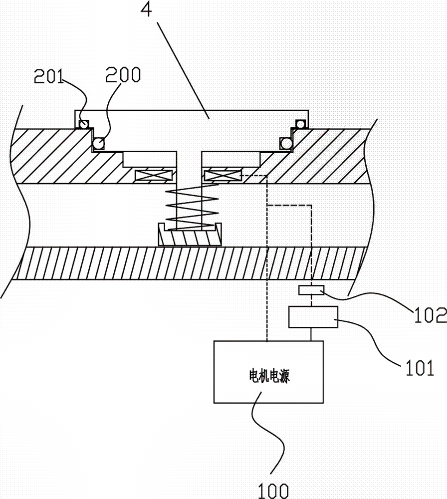
[0013] The present invention will be described in further detail below in conjunction with accompanying drawing and specific embodiment: see Figure 1 to Figure 4 , a lifter motor, including a motor power supply 100 for powering the lifter motor, a casing cavity 3 and an end cover 2 connected to the casing cavity 3, the end cover 2 is provided with an end cover hole 1, and the The end cover hole 1 communicates with the inside of the casing cavity 3 for dissipating the heat generated by the motor of the lifter during operation.

[0014] A step 11 is set on the end cover hole 1, a guide frame 10 is arranged in the end cover hole 1, and a sealing cover 4 for sealing the end cover hole 1 is slidably arranged in the guide frame 10, the sealing cover 4 includes a permanent magnet 40 provided at one end thereof, an upper end cap 41 for sealing the end cap hole 1 and a guide column 42 connecting the permanent magnet 40 and the upper end cap 41, and the upper end cap 41 includes a firs...


PUM


Abstract

The invention discloses a window lifter motor, which comprises a motor power supply, a casing cavity and an end cover. The end cover is provided with an end cover hole, and a step is arranged on the end cover hole. The inner slide is provided with a sealing cover, the sealing cover includes a permanent magnet arranged at one end, an upper end cover and a guide post, the upper end cover includes a first part and a second part matched with the step, and a first part is arranged on the side wall of the first part. The sealing ring is provided with a second sealing ring on the lower side of the second part, and also includes an electromagnet, and the electromagnet is arranged above the permanent magnet. The invention only opens the end cover hole to dissipate heat when the motor is turned on, and when the lifter motor is turned off, the end cover hole will not be closed immediately but will be closed after a delay, so that the heat in the casing cavity can be fully absorbed At the same time, it prevents the problem of water and dust entering the motor of the lifter when heat dissipation is not required.

Description

technical field [0001] The invention relates to the field of automotive window lifters, and more specifically, to a lifter motor. Background technique [0002] At present, the ventilating method of many small-voltage (operating voltage not greater than 36V) motors in China is to open a vent hole on the motor end cover to connect with the casing cavity, and then connect a vent pipe to the vent hole to communicate with the outside. The air pipe, after being connected to the casing cavity through the end cover hole, can discharge the heat generated by the motor rotor into the air to play a cooling role. In addition, when the air pipe faces downward, it can also achieve a certain waterproof effect. [0003] Although the ventilation tube of the motor can play the function of heat dissipation and cooling at present, it also has a certain waterproof function. However, when the water flow is large, or the motor is soaked in water, the water can still flow into the cavity of the mo...

Claims


Application Information

Patent Timeline
Patent Type & Authority Patents(China)
IPC IPC(8): H02K5/20H02K5/10
CPCH02K5/10H02K5/20
Inventor 陈世奇
Owner 宁波世通汽车零部件有限公司
Learn More