
Line laser scanning-based sand blasting robot automatic path generation method

A path generation and robot technology, applied in the direction of instruments, details involving 3D image data, image data processing, etc., can solve the problems that the template cannot be input in advance, the generation of processing paths cannot be discussed, and the detection of workpieces cannot be realized, etc., to achieve Broad application prospects and economic benefits, low cost, and the effect of speed block

Active Publication Date: 2016-02-24
SOUTHEAST UNIV
View PDF4 Cites 66 Cited by
  • Summary
  • Abstract
  • Description
  • Claims
  • Application Information

AI Technical Summary

Problems solved by technology

[0004] The current machine vision system usually uses a visible light source, which can be used to compare the image processing of the fixed template input in advance. For non-standard parts, the template cannot be input in advance. Therefore, the detection of the workpiece cannot be realized based on this, and the generation of the processing path is more difficult. is out of the question

Method used


Image

  • Line laser scanning-based sand blasting robot automatic path generation method
  • Line laser scanning-based sand blasting robot automatic path generation method
  • Line laser scanning-based sand blasting robot automatic path generation method

Examples


Embodiment Construction

[0061] The technical solutions of the embodiments of the present invention will be further described below in conjunction with the accompanying drawings.

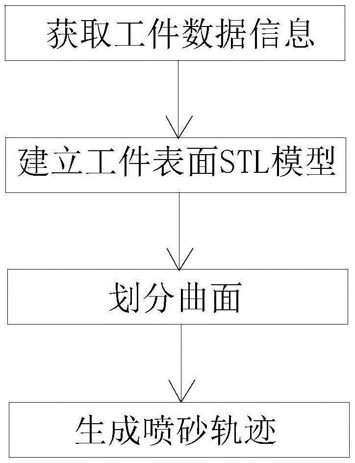
[0062] Such as figure 1 As shown, a method for generating an automatic path of a sandblasting robot based on line laser scanning in an embodiment of the present invention includes the following steps:

[0063] The first step: obtain workpiece data information: use 2D laser scanning to obtain the scanning sampling point data information on the surface of the workpiece to be sandblasted;

[0064] The second step: establish the STL model of the workpiece surface: through point cloud preprocessing, establish the STL model of the surface of the workpiece to be sandblasted;

[0065] Step 3: Divide the surface: extract and use the geometric and topological features of the STL model on the surface of the workpiece to divide the surface of the workpiece into several planes without holes;

[0066] Step 4: Generate sandblasting traj...


PUM


Abstract

The invention discloses a line laser scanning-based sand blasting robot automatic path generation method. The method comprises the following steps: 1, workpiece data information obtaining: obtaining data information of scanning sampling points on the surface of a workpiece to be sand blasted by adopting a 2D laser scanning manner; 2, workpiece surface STL model establishment: establishing a to-be-sand blasted workpiece surface STL model through point cloud pre-processing; 3, curved surface division: extracting and utilizing the geometrical characteristics and topological characteristics of the workpiece surface STL model so as to divide the curved surface of the workpiece into a plurality of planes without cavities; and 4, sand blasting track generation: constructing a characteristic frame according to the workpiece surface STL model and generating sand blasting tracks by adopting a cut plane projection method.

Description

technical field [0001] The present invention relates to a method for generating an automatic path for a sandblasting robot, in particular to a method for generating an automatic path for a sandblasting robot based on line laser scanning, in particular to a method for automatically generating a path for a sandblasting robot to blast an unknown model workpiece . Background technique [0002] For large-scale steel structure weldments, since the products are close to customized products, the shapes of the workpieces processed each time are different; surface pre-treatment is required to clean the surface oxide layer. At present, the combination of steel sand and lead sand is used, and 0.8MPa compressed air is used to blow the steel sand and throw it to the surface of the workpiece at high speed to realize the sandblasting work on the surface. Due to the high kinetic energy of sand, it is easy to cause injury to personnel when manually holding a sand gun at present. At the same...

Claims


Application Information

Patent Timeline
Patent Type & Authority Applications(China)
IPC IPC(8): G06T17/30
CPCG06T17/30G06T2200/04
Inventor 周波吴宝举孟正大戴先中韩明瑞徐龙
Owner SOUTHEAST UNIV
Learn More