
Constant-temperature and constant-humidity ice-source heat pump unit

A constant temperature and humidity, ice source technology, applied in the direction of household heating, heating methods, lighting and heating equipment, etc., can solve the problems of high energy consumption, high cost, and large power consumption of refrigeration systems for cooling and heating, and achieve the goal of replacing High thermal efficiency, compact structure, and the effect of reducing energy consumption

Inactive Publication Date: 2016-02-24
CHONGQING BINGYUANHONG ENERGY SAVING TECH DEV CO LTD
View PDF0 Cites 0 Cited by
  • Summary
  • Abstract
  • Description
  • Claims
  • Application Information

AI Technical Summary

Problems solved by technology

[0002] The existing constant temperature and humidity units all adopt the air-cooled structure of the outdoor unit, the refrigeration system uses a compressor, the heating system uses a finned electric heater, and the constant humidity system uses a humidifier imported from the indoor unit. This type of unit has the following problems: the electric heating system and the refrigeration system consume a lot of power, especially the electric heating system is more than twice that of the refrigeration system, and the side effect of dehumidification will also occur during cooling , the cost of the whole unit is high, the environmental requirements for the unit are also high, and the cooling and heating energy consumption is relatively large

Method used


Image

  • Constant-temperature and constant-humidity ice-source heat pump unit

Examples


Embodiment Construction

[0009] In order to make the technical means, creative features, goals and functions achieved by the present invention clearer and easier to understand, the present invention will be further elaborated below in conjunction with the accompanying drawings and specific embodiments:

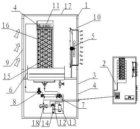
[0010] As shown in Figure 1, the present invention includes a refrigerant agent external unit 1 and a constant temperature and humidity coil fan 2, and the refrigerant agent external unit 1 includes an outer unit casing 3, a filling chamber 4, a fan 5, an ice source solution accumulation pool 6, The water-fluorine exchanger 7 and the circulating water pump 8 are provided with an air inlet 9 and an air outlet 10 on the side walls of the outer machine casing 3 on both sides of the filling chamber 4, and the fan 5 is fixed at the air outlet 9 of the outer machine casing 3. The ice source solution accumulation pool 6 is installed in the outer machine housing 3 and is located directly below the filling cham...


PUM


Abstract

The invention provides a constant-temperature and constant-humidity ice-source heat pump unit, which comprises a refrigerant outer unit and a constant-temperature and constant-humidity coil fan; the refrigerant outer unit comprises an outer unit housing, a filling chamber, a fan, an ice-source solution accumulating tank, a water-fluorine exchanger and a circulating water pump; a refrigerant port of the water-fluorine exchanger is connected with a refrigerant pipe inlet of the constant-temperature and constant-humidity coil fan through a valve bank; a refrigerant return port of the water-fluorine exchanger communicates with a reversing four-way valve; amongst the other three ports of the reversing four-way valve, one port communicates with an outlet of a compressor, while the other port communicates with an inlet of the compressor through a vapor-liquid separator and the rest one port communicates with a refrigerant return pipe of the constant-temperature and constant-humidity coil fan. The constant-temperature and constant-humidity coil fan has the advantages of compact structure and low cost; further, a refrigerating medium that may not be frozen at 30 DEG C below zero exchanges heat with air as a refrigerant or a heating agent, and the generated refrigerant is used for the constant-temperature and constant-humidity unit to refrigerate or heat; as a result, the energy consumption is remarkably reduced; moreover, the constant-temperature and constant-humidity ice-source heat pump unit is adaptive to cold weather environments.

Description

technical field [0001] The present invention belongs to the field of ice source technology, specifically a constant temperature and humidity unit. Background technique [0002] The existing constant temperature and humidity units all adopt the air-cooled structure of the outdoor unit, the refrigeration system uses a compressor, the heating system uses a finned electric heater, and the constant humidity system uses a humidifier imported from the indoor unit. This type of unit has the following problems: the electric heating system and the refrigeration system consume a lot of power, especially the electric heating system is more than twice that of the refrigeration system, and the side effect of dehumidification will also occur during cooling , the cost of the whole unit is high, the environmental requirements for the unit are also high, and the cooling and heating energy consumption is relatively large. Contents of the invention [0003] The purpose of the present inventi...

Claims


Application Information

Patent Timeline
IPC IPC(8): F24F5/00
CPCF24F5/0007
Inventor 李开年曾斌
Owner CHONGQING BINGYUANHONG ENERGY SAVING TECH DEV CO LTD
Learn More