Planar permanent-magnetic working table

A permanent magnet workbench and plane technology, applied in the direction of manufacturing tools, metal processing equipment, metal processing machinery parts, etc., can solve the problems of time-consuming, labor-intensive, small suction, limited use occasions, etc., to achieve a compact overall structure and improve the holding force , cost reduction effect

Inactive Publication Date: 2016-02-24
唐甬江
View PDF7 Cites 4 Cited by
  • Summary
  • Abstract
  • Description
  • Claims
  • Application Information

AI Technical Summary

Problems solved by technology

[0003] In the existing permanent magnetic chuck, it usually includes a housing, a panel, a pole core plate and a driving mechanism. The pole core plate is located on the housing under the panel, and it is arranged into various structures by magnetic conductive blocks and pole core blocks. , the more common form is: the pole core plate is fastened together by the magnetic conduction block and the pole core block at intervals, and the panel is composed of the magnetic conduction block and the magnetic isolation block arranged at intervals. When in use, the driving mechanism drives the pole core plate, The pole core plate is moved relative to the panel, so that the space above the panel finally realizes the alternating generation of magnetic field, but in this type of permanent magnetic chuck, since the pole core blocks are only distributed under the panel magnetic conductive block, when working, the Only a single magnetic circuit system is formed on the working surface, and the shell is flat. During the process of transmitting the magnetic force line, it is easy to lose a certain amount of magnetic force between the core plate and the shell, which makes its suction small and limits the application occasions.
At the same time, the more common driving mechanism is to use the handle for manual driving. On the one hand, it is time-consuming and laborious to operate. On the other hand, due to the limitation of the driving force, the permanent magnetic chuck cannot be made too large, so the holding force cannot meet some larger workpieces. fixed

Method used


Image

  • Planar permanent-magnetic working table
  • Planar permanent-magnetic working table
  • Planar permanent-magnetic working table

Examples


Embodiment Construction

[0017] The present invention will be further described in detail below in conjunction with the accompanying drawings and embodiments.

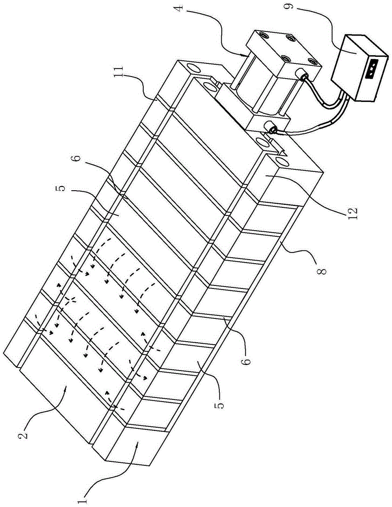
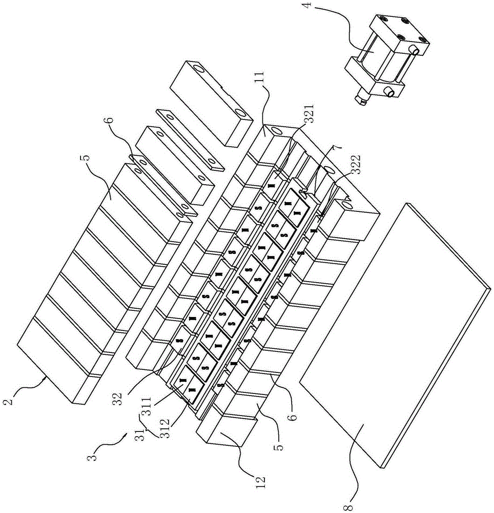
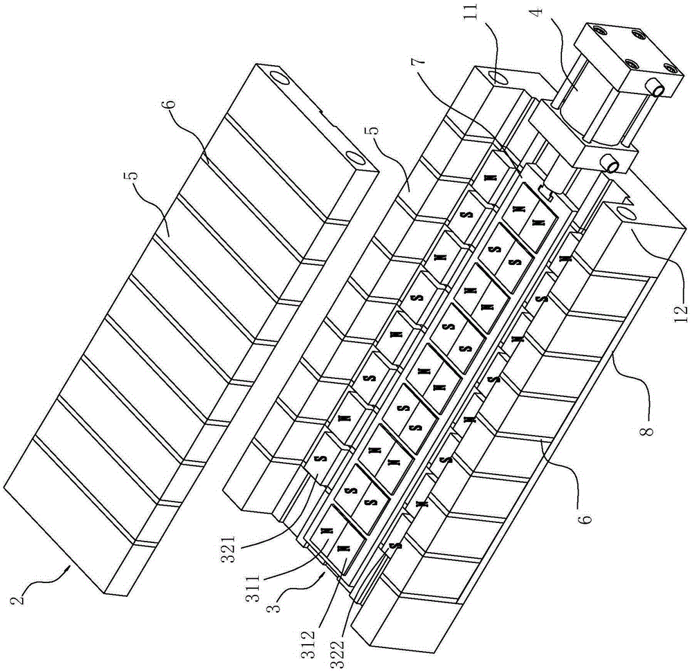
[0018] Such as Figure 1~4 As shown, the planar permanent magnet workbench includes a housing 1, a panel 2, a pole core plate 3 located in the housing 1 below the panel 2, and a driving mechanism, wherein the housing 1 and the panel 2 include magnetically conductive magnets arranged at intervals. Block 5 and magnetic isolation block 6; the drive mechanism adopts hydraulic cylinder 4 and a hydraulic station 9 for supplying oil to hydraulic cylinder 4; pole core plate 3 includes a plurality of bottom magnets 31 arranged longitudinally and adjacent to opposite polarities and at least A plurality of side magnets 32 located on one side of the bottom magnet 31 . In the present embodiment, a plurality of bottom magnets 31 are selected as nine bottom magnets 31, and each bottom magnet 31 is fixed on a bottom plate 7 in a longitudinally spaced manner ...


PUM


Abstract

The invention relates to a planar permanent-magnetic working table. The planar permanent-magnetic working table comprises a shell, a panel, a pole core plate and a driving mechanism, wherein each of the shell and the panel comprises magnetism conductive blocks and magnetism isolating blocks which are longitudinally and alternately arranged; and the pole core plate comprises multiple bottom magnets and multiple side magnets which are located on at least one side of the bottom magnets. The planar permanent-magnetic working table is characterized in that the driving mechanism comprises a hydraulic cylinder; the longitudinal section of the shell is U-shaped; the side magnets are near to the vertical parts of the shell; either the bottom magnets or the side magnets can be drafted by the hydraulic cylinder to become variable magnets which can move longitudinally and horizontally; by adopting the above structure, with the same working area, the absorption force of the working table is much larger than that of a current permanent magnetic chuck; besides, the hydraulic cylinder is adopted by the driving mechanism, so that the whole structure is compact, and the operation is easy; and more bottom magnets can be designed according to requirements, so that the cost is lowered, and use requirements at different situations can be met.

Description

technical field [0001] The invention relates to a permanent magnet type magnetic force device, in particular to a planar permanent magnet workbench used for clamping workpieces in the field of mechanical processing. Background technique [0002] The permanent magnetic chuck adopts a permanent magnetic source. By controlling the external circulation of the magnetic source and the internal circulation of the magnetic source, the magnetic field alternately appears or closes on the working surface. According to this principle, it is usually made into a metal cutting machine tool. The suction cup or the magnet device for lifting uses the magnetic holding or closing of its working surface to realize the holding, fastening, positioning of the workpiece or to complete the loading and unloading of materials. Because it does not require electricity and does not generate temperature rise during use, and its use is relatively safe and reliable, it is widely used in machining and lifting...

Claims


Application Information

Patent Timeline
IPC IPC(8): B23Q3/154
CPCB23Q3/1546
Inventor 唐甬江
Owner 唐甬江
Why Eureka
Try Eureka