Pickup devices and robots

A suction device and suction cup technology, which is applied in the direction of manipulators, chucks, manufacturing tools, etc., can solve the problems of weakening vacuum degree, insufficient vacuum degree of vacuum suction cup, and influence of vacuum suction cup, so as to improve stability and reliability and increase suction success rate, increase the effect of the scope of application

Active Publication Date: 2017-07-28
易造机器人(深圳)有限公司
View PDF5 Cites 0 Cited by
  • Summary
  • Abstract
  • Description
  • Claims
  • Application Information

AI Technical Summary

Problems solved by technology

During the suction operation, when one or more vacuum chucks are not adsorbed to the plate with holes, the vacuum chuck will have a vacuum leak. Due to the large number of vacuum chucks, the places where vacuum leaks will also increase. After a period of time, the phenomenon of vacuum leakage will become more obvious, which will affect other vacuum chucks
At the same time, since each vacuum generator distributes 10 vacuum suction cups, the vacuum degree distributed by each suction cup is weakened, so that the vacuum degree is insufficient
[0003] To sum up, in the existing suction device, the vacuum degree of the vacuum suction cup is insufficient, and vacuum leakage is prone to occur, thereby reducing the suction success rate of the plate with holes, and seriously affecting the stability and reliability of the suction device.

Method used


Image

  • Pickup devices and robots
  • Pickup devices and robots
  • Pickup devices and robots

Examples


Embodiment Construction

[0022] It should be understood that the specific embodiments described here are only used to explain the present invention, not to limit the present invention.

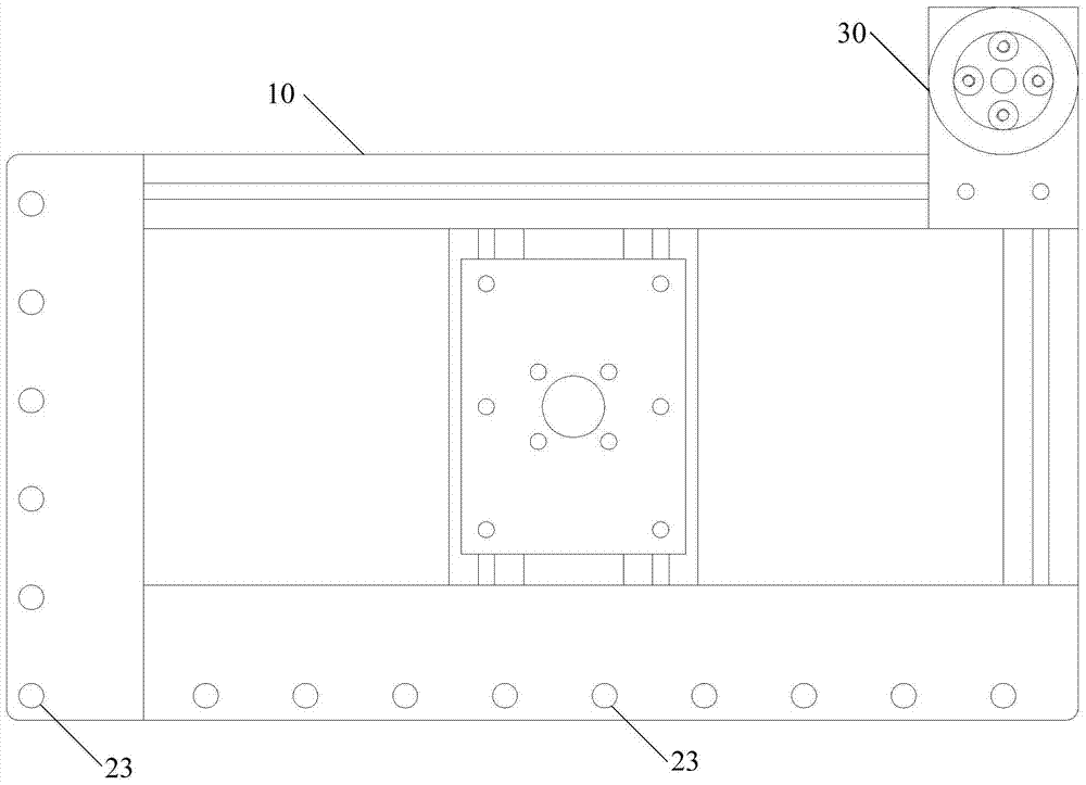
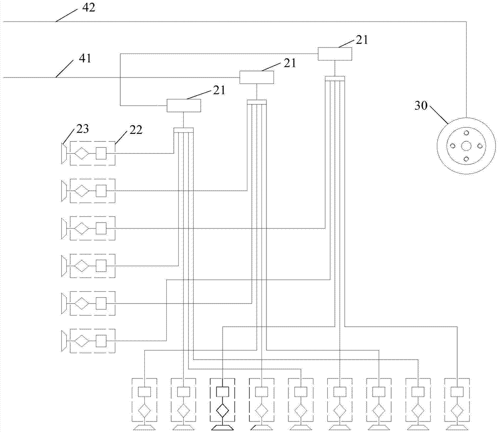
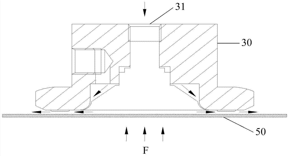
[0023] see Figure 1-Figure 3 , propose a first embodiment of the suction device of the present invention, wherein figure 1 It is a structural schematic diagram of the first embodiment of the suction device of the present invention, figure 2 It is a schematic diagram of the gas path of the suction device of the embodiment of the present invention; image 3 It is a working principle diagram of the non-contact suction cup according to the embodiment of the present invention. The suction device is applied to an automatic processing robot, and is mainly used for suctioning a flat plate with holes (such as a printed circuit board with holes). The suction device includes a substrate 10 and a vacuum suction component installed on the substrate 10 , the vacuum suction component includes at least two vacuum generators 21 ,...


PUM


Abstract

The invention discloses a suction device and a robot. The suction device comprises a base plate and a vacuum adsorption assembly installed on the base plate, wherein the vacuum adsorption assembly comprises at least two vacuum generators, a plurality of vacuum suction discs and a plurality of vacuum safety valves; each vacuum generator is connected with a plurality of vacuum suction discs; and each vacuum suction disc is connected with one vacuum safety valve. Through additionally arranging the vacuum safety valves for the vacuum suction discs, vacuum leakage in each vacuum suction disc is prevented, so that a vacuum degree in each vacuum suction disc is maintained, and then the suction success rate of a perforated flat plate is increased, and the stability and the reliability of the suction device are improved.

Description

technical field [0001] The invention relates to the technical field of automatic production, in particular to a suction device and a robot. Background technique [0002] In the process of automatic processing and production, robots are usually used to carry and process workpieces. For flat plates with holes, such as printed circuit boards with holes, the suction device of the robot is usually used for suction and transportation. The existing suction device includes a substrate, multiple vacuum generators and multiple vacuum chucks installed on the substrate, each vacuum generator is usually connected with 10 vacuum chucks, and one suction device usually has 50 vacuum chucks. During the suction operation, when one or more vacuum chucks are not adsorbed to the plate with holes, the vacuum chuck will have a vacuum leak. Due to the large number of vacuum chucks, the places where vacuum leaks will also increase. After a period of time, the phenomenon of vacuum leakage will beco...

Claims


Application Information

Patent Timeline
Patent Type & Authority Patents(China)
IPC IPC(8): B25J15/06
CPCB25J15/0616
Inventor 吴琼海董加归
Owner 易造机器人(深圳)有限公司
Why Eureka
Try Eureka