Waste chip cleaning type processing working table

A workbench and table body technology, which is applied in the field of machining devices, can solve the problems of inconvenient cleaning and recycling of waste materials.

Inactive Publication Date: 2016-02-17
LUZHOU YUANCHENG ENG MACHINERY CO LTD
View PDF4 Cites 5 Cited by
  • Summary
  • Abstract
  • Description
  • Claims
  • Application Information

AI Technical Summary

Problems solved by technology

[0004] The purpose of the present invention is to provide a waste cleaning type processing workbench, which solves the problem in the prior art that the waste generated during the processing of parts is inconvenient to clean and recycle, and realizes convenient and fast cleaning and recovery of waste on the machining workbench. purpose of waste

Method used


Image

  • Waste chip cleaning type processing working table
  • Waste chip cleaning type processing working table

Examples


Embodiment 1

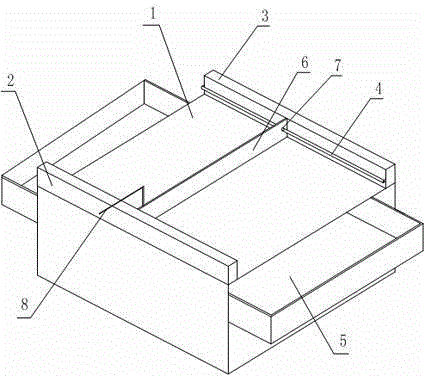
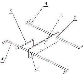
[0016] like figure 1 and figure 2 The shown waste cleaning type processing workbench includes a square table body 1, the left and right side of the table body 1 are provided with drawers 5, and the front and rear edges of the upper surface of the table body 1 are A first baffle plate 2 and a second baffle plate 3 perpendicular to the upper surface of the table body 1 are respectively provided, and the inner surfaces of the first baffle plate 2 and the second baffle plate 3 are welded with protruding connecting rods 4 A scraper 6 is arranged between the two connecting rods 4, and both sides of the scraper 6 are provided with through holes 7 through which the connecting rod 4 can pass, and the bottom edge of the scraper 6 is in contact with the The upper surface of the table body 1 is adjacent, and the push rod 8 extending to the outside of the table body 1 is fixedly connected to the scraper 6 . In this embodiment, the connecting rods 4 on the left and right sides respective...

Embodiment 2

[0018] like figure 1 and figure 2 In the waste cleaning type processing workbench shown, on the basis of Embodiment 1, the height of the scraper 6 is the same as that of the first baffle 2 and the second baffle 3, and the scraper 6 The width is the width between the first baffle plate 2 and the second baffle plate 3 . When performing parts processing in this embodiment, the scraper 6 is pushed to the edge of the table body 1, and its height is set to be consistent with the height of the first baffle plate 2 and the second baffle plate 3 , to prevent the scraper 6 from being too high to interfere with the operator's actions and affect the processing of the machine parts; and the width of the scraper 6 is set to be between the first baffle 2 and the second baffle 3 The width can push down the remaining waste materials to the maximum extent into the drawer 5 .


PUM


Abstract

The invention discloses a waste chip cleaning type processing working table which comprises a square table body, wherein left and right side surfaces of the table body are provided with drawers; front and rear side edges of the upper surface of the table body are respectively provided with a first baffle plate and a second baffle plate perpendicular to the upper surface of the table body; inside surfaces of the first baffle plate and the second baffle plate are fixed with bulged connecting rods; a scraper plate is arranged between the two connecting rods; through holes capable of allowing the connecting rods to pass through are formed in both sides of the scraper plate; the bottom side of the scraper plate is adjacent to the upper surface of the table body; and a pushing rod extending to the outside of the table body is fixedly connected on the scraper plate. The invention aims to provide the waste chip cleaning type processing working table which solves the problem that in a part processing process in the prior art, the generated waste chips are inconvenient for being cleaned and recycled, so that the purpose of conveniently and quickly cleaning, and recycling the waste chips on the mechanical processing working table is realized.

Description

technical field [0001] The invention relates to the field of machining devices, in particular to a waste cleaning type processing workbench. Background technique [0002] Mechanical components, also known as mechanical components, are inseparable individual parts that make up machinery and machines. It is the basic unit of machinery, such as various bearings, valves, linkages, transmissions, and meshing devices. Long before the appearance of modern machinery, there were already many prototypes of mechanical parts, but as a subject, mechanical parts were separated from mechanical construction and mechanics. With the development of the machinery industry, the emergence of new design theories and methods, new materials, and new processes, mechanical parts have entered a new stage of development, and are now inseparable from people's daily lives. However, for mechanical parts, it must be processed on a machine tool or workbench with a certain precision processing capability, an...

Claims


Application Information

Patent Timeline
Patent Type & Authority Applications(China)
IPC IPC(8): B25H1/00B25H1/12B08B1/00
CPCB25H1/00B08B1/005B25H1/12
Inventor 马赟
Owner LUZHOU YUANCHENG ENG MACHINERY CO LTD
Why Eureka
Try Eureka