
A heavy-duty UAV

A drone and arm technology, applied in the field of drones, can solve problems such as unsafe take-off and landing, light jitter, low structural safety, etc., to improve stability and safety, reduce vibration impact, and meet flight requirements Effect

Active Publication Date: 2017-09-15
HUNAN AIRTOPS INTELLIGENT TECH CO LTD
View PDF9 Cites 1 Cited by
  • Summary
  • Abstract
  • Description
  • Claims
  • Application Information

AI Technical Summary

Problems solved by technology

[0003] (1) The pulling force of the existing aircraft is not enough to meet the large pulling force demand of the heavy load
[0004] (2) The existing aircraft does not have a mounting platform specially suitable for large-mass mounting
Since the volume, mass, and fixed point of each large-mass mounted object are different, the centers of gravity of each large-mass mounted object are also different. The flight center of gravity of the man-machine is unstable, which changes the flight attitude of the man-machine, which directly affects the stability and safety of the drone.
[0005] (3) The shock absorption effect of the mounting platform of the existing aircraft is not good, and cannot meet the shock absorption requirements of large loads
The drone will cause a certain vibration environment during the flight, which has a great impact on the mounted objects of the drone with high stability requirements; especially the heavy-duty and high-power aircraft will definitely generate greater Flight vibrations, if these vibrations are not effectively damped and filtered, it is bound to seriously affect the normal operation of large-mass mounts (such as unstable operations, blurred cameras, light shakes, device damage, etc.)
[0006] (3) The structure setting of the existing aircraft is not scientific and reasonable, and the unfolded size is too large, the folding method is unreasonable, the transportation is difficult, and it is inconvenient to carry
[0007] (4) The existing aircraft is limited by the number of batteries that can be carried or the weight of the take-off, and the time in the air is short, which cannot achieve the ideal working effect, especially not suitable for the flight requirements of heavy loads
[0008] (5) The existing aircraft has a low flight safety factor, low structural safety, unsafe take-off and landing, and cannot cope with emergencies with heavy loads

Method used


Image

  • A heavy-duty UAV
  • A heavy-duty UAV
  • A heavy-duty UAV

Examples


Embodiment Construction

[0045] The present invention will be described in further detail below in conjunction with specific embodiments and accompanying drawings.

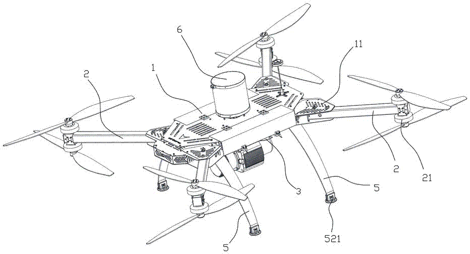
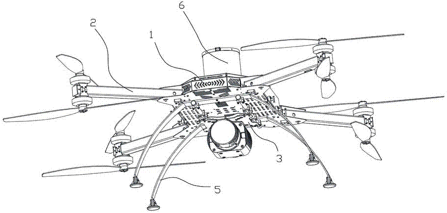
[0046] Such as Figure 1 to Figure 10 As shown, the present invention provides a large-load unmanned aerial vehicle, comprising a fuselage assembly 1 and more than three arm assemblies 2, one end of each arm assembly 2 is connected with the fuselage assembly 1, each The other end of the arm assembly 2 is provided with two coaxially arranged rotor assemblies 21, each rotor assembly 21 includes a propeller 211 and a motor 212, and the bottom of the fuselage assembly 1 is provided with a The mounting platform 3. In order to realize the requirement of large load and improve the lift force of the UAV, the present invention is provided with more than three machine arm assemblies 2, and at the same time, each machine arm assembly 2 is provided with two sets of coaxially arranged propellers 211 and a The motor 212 adopts the power mode of up an...


PUM


Abstract

The invention discloses a heavy-load unmanned aerial vehicle. The heavy-load unmanned aerial vehicle comprises a fuselage assembly and more than three arm assemblies, one end of each arm assembly is connected with the fuselage assembly, the other end of each arm assembly is provided with two coaxially arranged rotor components, each rotor component comprises a propeller and a motor, and the bottom part of the fuselage assembly is provided with a loading platform for loading articles. The heavy-load unmanned aerial vehicle has the advantages of large pulling force, capability of adjusting flight gravity center, good loading damping effect, good flight efficiency, high security and carriage convenience, and the heavy-load unmanned aerial vehicle can meet the heavy load demands.

Description

technical field [0001] The invention mainly relates to the field of unmanned aerial vehicles, in particular to a heavy-duty unmanned aerial vehicle. Background technique [0002] In the field of existing rotor UAVs, there are very few types of heavy-duty aircraft, most of which do not exceed 3KG. For some large-mass mounts, there is no suitable flying platform. At the same time, the following technical problems generally exist in the existing flight platforms: [0003] (1) The pulling force of the existing aircraft is not enough to meet the large pulling force demand of the heavy load. [0004] (2) The existing aircraft does not have a mounting platform specially suitable for large-mass mounting. Since the volume, mass, and fixed point of each large-mass mounted object are different, the centers of gravity of each large-mass mounted object are also different. The flight center of gravity of the man-machine is unstable, which changes the flight attitude of the man-machine,...

Claims


Application Information

Patent Timeline
Patent Type & Authority Patents(China)
IPC IPC(8): B64C27/10B64C27/37B64C1/00B64D47/00B64C27/12B64D27/24
CPCY02T50/60
Inventor 罗世彬许良晓吴雷
Owner HUNAN AIRTOPS INTELLIGENT TECH CO LTD
Learn More