A dynamic descending speed limiting device for a high-altitude cable climbing robot

A speed-limiting device and robot technology, applied in motor vehicles, brakes, transportation and packaging, etc., can solve the problems of slow return to the ground, attenuation of braking force, failure to achieve speed-limited braking, etc. The effect of high utilization and integration

Active Publication Date: 2017-06-23
NANJING UNIV OF POSTS & TELECOMM
View PDF5 Cites 0 Cited by
  • Summary
  • Abstract
  • Description
  • Claims
  • Application Information

AI Technical Summary

Problems solved by technology

[0005] The cables usually have different angles. Most of the existing technologies adopt constant friction braking measures, and the friction force cannot change with the speed of the descent.
The main disadvantage of this constant friction technique is that it cannot adapt to cables with different inclination angles.
If the braking force is set too small, when climbing the vertical cable, the braking force may not be able to achieve the effect of speed limit braking; However, when climbing the inclined cable, due to too much braking force, it may not be possible to return to the ground, or the speed of returning to the ground may be too slow
[0006] In addition, since the braking force cannot be changed according to the change of the descending speed, its descending speed is uncontrollable
[0007] Moreover, the robot needs to fall back to the ground at a height of several hundred meters, so the speed limit braking device needs to work for a long time, and the braking force cannot produce a large attenuation

Method used


Image

  • A dynamic descending speed limiting device for a high-altitude cable climbing robot
  • A dynamic descending speed limiting device for a high-altitude cable climbing robot
  • A dynamic descending speed limiting device for a high-altitude cable climbing robot

Examples


Embodiment Construction

[0056] The present invention will be further described in detail below in conjunction with the accompanying drawings and specific preferred embodiments.

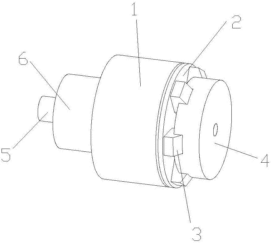
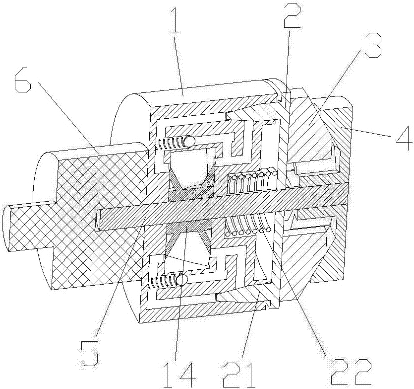
[0057] Such as figure 1 and figure 2 As shown, a dynamic descending speed limiting device for a high-altitude cable climbing robot includes a stator 1, a rotor 4, a mandrel 5, a speed increaser 6, an impeller 14, a compression spring 22, a sliding disc 2, an inertia block 3, Steel ball 26 and spring 15.

[0058] The speed increaser 6, the stator 1, the sliding disc 2 and the rotor 4 are coaxially sleeved on the outer periphery of the mandrel 5 sequentially from left to right. Wherein, the speed increaser 6 can be set as required. When the speed increaser 6 is provided, the speed increaser 6 is preferably fixedly connected to the end surface of the stator 1 .

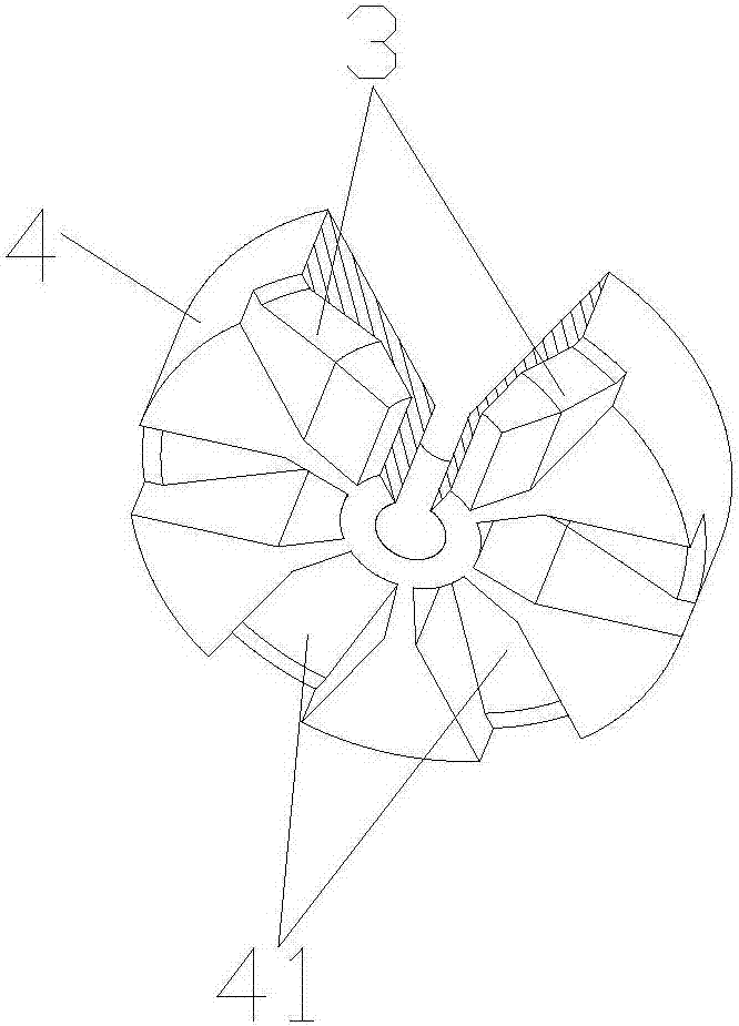
[0059] Such as Figure 3 to Figure 6 As mentioned above, the side of the rotor 4 adjacent to the sliding plate 2 is evenly provided with several inclined chute 4...


PUM


Abstract

The invention discloses a dynamic descending speed limiting device for a high-altitude cable climbing robot, which comprises a stator, a rotor and a mandrel. The inertia block matched with the chute slope; each inertia block fits the sliding plate under the action of the compression spring; the sliding plate is provided with a conical spool; the stator is provided with a hydraulic chamber, an inner blind hole and The outer blind hole; the hydraulic cavity is equipped with an impeller; the inner blind hole includes a tapered hole, and a steel ball connected with the spring is arranged in the inner blind hole; the outer blind hole is provided with a tapered valve hole matching the tapered valve core . After adopting the above-mentioned structure, the structure is simple and compact, the braking force can change dynamically and adaptively with the change of the descending speed, the lower limit speed is controllable, the braking resistance comes from the damping force generated when the fluid passes through the damping hole, and there is no pure mechanical friction The problem of heat attenuation is solved, and it can perform long-term and long-distance braking, and has high promotion value.

Description

technical field [0001] The invention relates to a speed limiting device, in particular to a dynamic descending speed limiting device for a high-altitude cable climbing robot. Background technique [0002] Cable-stayed bridge cable climbing robots work in extreme high-altitude environments. Generally, the climbing and descending of the robot is realized through the control system. There are many unfavorable factors such as wind load and vibration in the high-altitude environment, so the failure of the electrical control system occurs occasionally. When an electrical failure occurs, the robot is in a state of out of control. Under the action of gravity acceleration, it will do free fall and fall from the cable at a very fast speed, which will easily cause extremely serious safety accidents. [0003] To solve this problem, it is very important to design a device that can limit the speed in case of power failure. [0004] The invention combines the research results of mechanic...

Claims


Application Information

Patent Timeline
Patent Type & Authority Patents(China)
IPC IPC(8): B62D57/024B60T10/00
Inventor 徐丰羽胡金龙蒋国平
Owner NANJING UNIV OF POSTS & TELECOMM
Why Eureka
Try Eureka