
Measuring pipe dredge device

A technology for measuring pipelines and tubular shapes, which is applied in the field of measuring pipeline dredging devices, which can solve problems such as leakage of toxic media, blockage of pressure measurement, and endangering the safety of maintenance personnel, etc., and achieve the effects of thorough pipeline dredging, simple and labor-saving operation, and prevention of medium leakage

Active Publication Date: 2017-07-14
SHANGHAI MEISHAN IRON & STEEL CO LTD
View PDF6 Cites 0 Cited by
  • Summary
  • Abstract
  • Description
  • Claims
  • Application Information

AI Technical Summary

Problems solved by technology

[0004] Coke oven or blast furnace gas contains a large amount of easily bonded coal tar in the combustion medium of boilers in thermal power plants. During pressure measurement, the sampling pipeline has strong adhesion of coal tar, especially for continuous measurement and long-term operation. Coal tar adheres to the The mouth of the measuring pipe will gradually block the pressure hole, causing the instrument to fail to work normally. Since the gas pressure measuring point is related to the boiler MFT protection, the problem of pressure measuring blockage will bring certain hidden dangers to the safe operation of the boiler.
The original dredging method is that the maintenance personnel remove the measuring pipe joints and manually dredge. The disadvantages are 1. It causes a large amount of toxic medium to leak and endangers the safety of the maintenance personnel; 2. Before dredging, the boiler MFT protection must be withdrawn; 3. The equipment for the maintenance personnel is increased. Maintenance

Method used


Image

  • Measuring pipe dredge device
  • Measuring pipe dredge device
  • Measuring pipe dredge device

Examples


Embodiment Construction

[0026] The present invention will be further described below in conjunction with the accompanying drawings.

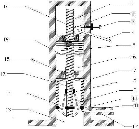
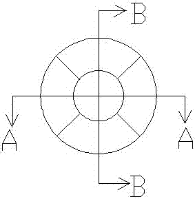
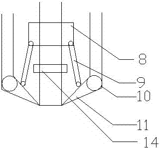
[0027] Such as Figure 1-4 As shown, the measurement pipeline dredging device of the present embodiment comprises a tubular shell with one end closed and one end open, a shovel bracket 7 is installed inside the tubular housing, and an umbrella-shaped shovel 11 is installed on the described shovel bracket. The blade bracket is connected to the pulling drive device, and the umbrella-shaped blade is also connected to the shrinking device.

[0028] In the device for dredging the measuring pipeline, the pulling drive device includes a displacement chamber 6 arranged inside the tubular housing, a blade connecting rod 18 connected to the blade bracket, and the blade rod 18 connected to the blade bracket. The middle part of the knife connecting rod is provided with a fixed block 16, and the fixed block is located in the displacement chamber, and the upper part of the fixed bl...


PUM


Abstract

The invention provides a measuring pipeline dredging device. The invention comprises a tubular shell with one end closed and one end open, characterized in that: a shovel bracket is installed inside the tubular shell, an umbrella-shaped shovel is installed on the shovel support, and the shovel support is connected to a lifting The drive device, the umbrella-shaped blade is also connected to the retraction device. The invention can quickly remove the clogging and viscous attachments of the pressure taking port on-line, and can ensure the continuous and undisturbed measurement of the pressure.

Description

[0001] Technical field: [0002] The invention relates to a device for dredging a measuring pipeline for pressure measurement in viscous substances or harsh environments that are easy to stick (such as gas, heavy oil, etc.). [0003] Background technique: [0004] Coke oven or blast furnace gas contains a large amount of easily bonded coal tar in the combustion medium of boilers in thermal power plants. During pressure measurement, the sampling pipeline has strong adhesion of coal tar, especially for continuous measurement and long-term operation. Coal tar adheres to the The mouth of the measuring pipe will gradually block the pressure hole, causing the instrument to fail to work normally. Since the gas pressure measuring point is related to the MFT protection of the boiler, the blockage of the pressure measurement will bring certain hidden dangers to the safe operation of the boiler. The original dredging method is that the maintenance personnel remove the measuring pipe joint...

Claims


Application Information

Patent Timeline
Patent Type & Authority Patents(China)
IPC IPC(8): B08B9/027G01L11/00
Inventor 成涛陆洪波
Owner SHANGHAI MEISHAN IRON & STEEL CO LTD
Learn More