
Automatic spraying device for tubular metal heat exchanger outer walls

An automatic spraying and heat exchanger technology, applied in the direction of the spraying device, can solve the problems of uneven spraying speed, time-consuming and laborious, easy to settle, etc., and achieve the effect of reducing labor intensity, improving spraying quality, and increasing construction speed

Active Publication Date: 2016-02-03
武汉钢铁有限公司
View PDF5 Cites 9 Cited by
  • Summary
  • Abstract
  • Description
  • Claims
  • Application Information

AI Technical Summary

Problems solved by technology

The above method not only has slow construction speed, uneven spraying thickness and unstable quality, but also the phenomenon of repeated spraying in multiple areas
For cylindrical tubular metal heat exchanger steel pipes, due to the arc-shaped construction surface, spraying with a single-nozzle hand-held spray gun will inevitably result in part of the coating being unable to be effectively sprayed on the working surface, and a large amount of coating will be generated in the air Suspended particles are not only time-consuming and labor-intensive, but also cause a lot of waste of paint, and may also cause great harm to the health of operators
At the same time, compared with paint, inorganic non-metallic coatings used for metal heat exchanger coatings have problems such as high density, short suspension time, and easy precipitation.
At present, the existing single-nozzle hand-held spray guns used for paint spraying are directly used to spray inorganic non-metallic coatings, which may easily cause uneven spray speed and gun blockage.
In addition, the assembled multi-row arrayed tubular metal heat exchanger has a small distance between adjacent steel pipes and a large depth, so the operable space is very limited, and manual painting or hand-held spray guns cannot be used for construction

Method used


Image

  • Automatic spraying device for tubular metal heat exchanger outer walls
  • Automatic spraying device for tubular metal heat exchanger outer walls
  • Automatic spraying device for tubular metal heat exchanger outer walls

Examples


Embodiment Construction

[0030] The implementation of the present invention will be described in detail below in conjunction with the accompanying drawings, but it does not constitute a limitation of the present invention, and is only used as an example. At the same time, the advantages of the present invention will become clearer and easier to understand through the description.

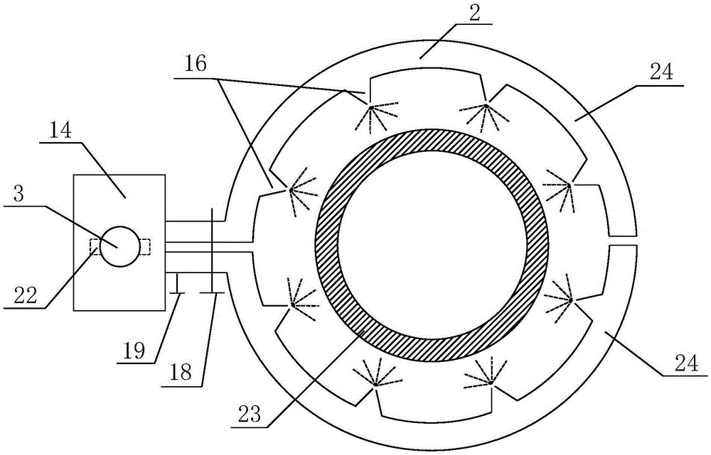
[0031] Such as Figures 1 to 3 As shown, the automatic spraying equipment for the outer wall of the tubular metal heat exchanger according to the present invention is mainly composed of three parts: a paint tank 1 , a spray head 2 and a vertical pole 3 .

[0032] Inorganic non-metallic paint is housed in paint tank 1, and circular top cover 7 is arranged on paint tank 1, and feed port 9 is opened on top cover 7, and described feed port 9 communicates with atmosphere; Top cover 7 is also provided with The mixer 8, the blades of the mixer 8 go deep into the paint, and are used to stir the paint evenly.

[0033] The nozzle 2...


PUM


Abstract

The invention discloses an automatic spraying device for tubular metal heat exchanger outer walls. The automatic spraying device mainly comprises a spraying tank and a spraying head. The spraying head is of a tubular structure movably nested on a heat exchange steel pipe. One end of the spraying head is of an annular structure, and the other end of the spraying head is connected with a vertical rod. The vertical rod is parallel to the heat exchange steel pipe. The spraying head is communicated with the spraying tank through a material pipe. A plurality of spraying nozzles are evenly distributed on the inner wall of the annular structure in the circumferential direction. The spraying nozzles are right opposite to the outer wall of the heat exchange steel pipe. The spraying head can move along the vertical rod so as to drive the annular structure to axially displace along the heat exchange steel pipe. Coatings are sprayed to the outer wall of the heat exchange pipe uniformly, the spraying efficiency is high, and the automatic spraying device can be used for construction of coating of the outer walls of tubular metal heat exchangers arrayed in rows.

Description

technical field [0001] The invention relates to spraying equipment, in particular to an automatic spraying equipment for the outer wall of a tubular metal heat exchanger. Background technique [0002] Heat exchanger is a chemical equipment commonly used in chemical industry, oil refining, food, light industry, energy, pharmaceutical, machinery and other industrial fields. Its main function is to realize heat conversion, and it is one of the main equipment to improve energy utilization. There are many types of heat exchangers, which can be divided into three categories according to different materials: metal heat exchangers, ceramic heat exchangers and plastic heat exchangers, among which metal heat exchangers are the most commonly used types of heat exchangers in industrial applications. The reason is that the metal material used in the metal heat exchanger has a high thermal conductivity and can have a high heat transfer efficiency. [0003] In the actual use process, due ...

Claims


Application Information

Patent Timeline
Patent Type & Authority Applications(China)
IPC IPC(8): B05B13/04B05B13/02B05B15/06
CPCB05B13/0278B05B13/041B05B15/62
Inventor 罗巍丁翠娇李明晖欧阳德刚韩斌朱善合宋中华王海清
Owner 武汉钢铁有限公司
Learn More