
MEMS (Micro Electro Mechanical Systems) electro-thermal actuator and manufacturing process thereof

A manufacturing process and actuator technology, applied in the field of MEMS, can solve the problems of small operating voltage, large working deformation, and fast response of MEMS electrothermal actuators, and achieve the effect of avoiding signal voltage interference, large deformation, and low power consumption

Inactive Publication Date: 2016-01-27
BEIJING INSTITUTE OF TECHNOLOGYGY
View PDF7 Cites 3 Cited by
  • Summary
  • Abstract
  • Description
  • Claims
  • Application Information

AI Technical Summary

Problems solved by technology

[0003] The purpose of the present invention is to provide a MEMS electrothermal actuator and its manufacturing process, which solves the technical problem of independent processing of the MEMS electrothermal actuator, and realizes that the working voltage of the MEMS electrothermal actuator is small and the working deformation in the energized state Large, low power consumption and fast response

Method used


Image

  • MEMS (Micro Electro Mechanical Systems) electro-thermal actuator and manufacturing process thereof
  • MEMS (Micro Electro Mechanical Systems) electro-thermal actuator and manufacturing process thereof

Examples


Embodiment Construction

[0025] The present invention will be described in more detail below with examples in conjunction with the accompanying drawings.

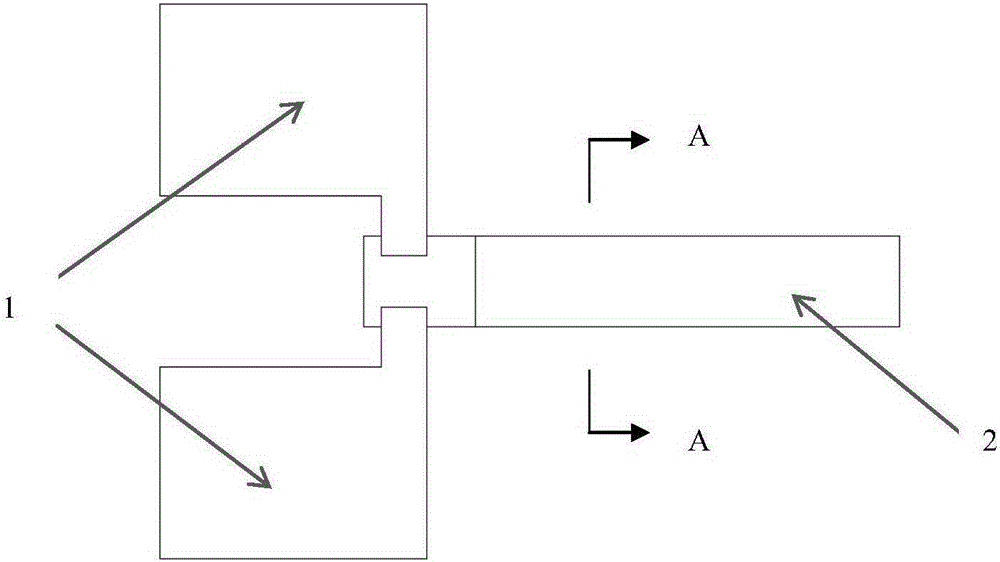
[0026] Such as figure 1 As shown, a MEMS electrothermal actuator of the present invention is a cantilever beam structure, the cantilever beam is composed of a pad 1 and a beam 2, the beam 2 has a fixed end and a cantilever end, and the pad 1 is located on both sides of the fixed end of the beam, which is The part that connects beam 2 with electricity. .

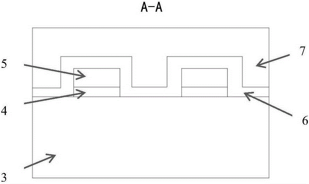
[0027] Such as figure 2 As shown, the beam 2 has a hierarchical structure. The beam 2 includes an upper layer 7, a middle layer 5, a lower layer 3, an adhesive layer 4 and an insulating layer 6. The thermal expansion coefficients of the upper layer material and the lower layer material are quite different. The difference in coefficients results in deformation of the beam 2, thus fulfilling the function of the actuator. The middle layer 5 is a heating layer, and the shapes of the middle layer ...


PUM

PropertyMeasurementUnit
thicknessaaaaaaaaaa
thicknessaaaaaaaaaa
crystal orientationaaaaaaaaaa

Abstract

The invention relates to an MEMS (Micro Electro Mechanical Systems) electro-thermal actuator and a manufacturing process thereof, and aims to solve the problem of independent machining and realize advantages of low working voltage, large deformation, low power consumption and quick response. The electro-thermal actuator is a cantilever beam, wherein a beam (2) comprises an upper layer (7), a middle layer (5), a lower layer (3), a bonding layer (4) and an insulating layer (6); materials of the upper layer and the lower layer are different in thermal expansion coefficients; the middle layer (5) is a heating layer; the bonding layer (4) is positioned between the middle layer (5) and the lower layer (3); the insulating layer (6) covers an upper surface of the middle layer (5); two electrodes are embedded into the insulating layer (6); the two electrodes are in contact with side faces of the two ends of a U-shaped upper part of the heating layer respectively; the two electrodes are integrated with the upper layer (7); and the bottom of a lower layer of a beam fixed end is a substrate layer.

Description

technical field [0001] The invention belongs to the technical field of MEMS, and in particular relates to a MEMS electrothermal actuator and a manufacturing process thereof. Background technique [0002] MEMS (MicroelectromechanicalSystems - Micro Electromechanical System) is an industrial technology that integrates microelectronics technology and mechanical engineering, and its operating range is in the micron range. The material of the existing MEMS electrothermal actuator is usually Cu-SiO 2 , Al-SiO 2 or Au-SiO 2 Several kinds. For the existing MEMS electrothermal actuator manufacturing process, a dedicated MEMS production line is used abroad. In China, MEMS electrothermal actuators are mainly processed on the integrated circuit process line. Since the MEMS electrothermal actuator is processed at the same time as the integrated circuit, most integrated circuit process lines are not compatible with copper and gold. The heating layer material in MEMS electrothermal ac...

Claims


Application Information

Patent Timeline
Patent Type & Authority Applications(China)
IPC IPC(8): B81B3/00B81C1/00
Inventor 宋荣昌关平陈庆森申跃跃吕永佳
Owner BEIJING INSTITUTE OF TECHNOLOGYGY
Learn More