
Retardation film and manufacturing method thereof, polarizing plate and image display device using same, 3D image display system using same

一种相位差薄膜、相位差层的技术,应用在偏振元件、其他家里用具、应用等方向,达到降低干涉条纹、降低界面反射、抑制干涉条纹的效果

Active Publication Date: 2019-11-05
DAI NIPPON PRINTING CO LTD
View PDF14 Cites 0 Cited by
  • Summary
  • Abstract
  • Description
  • Claims
  • Application Information

AI Technical Summary

Problems solved by technology

In general, there is a problem that interference fringes caused by thin film interference between the retardation layer and the transparent substrate are more likely to be seen than when the haze is 1.0% or more)

Method used


Image

  • Retardation film and manufacturing method thereof, polarizing plate and image display device using same, 3D image display system using same
  • Retardation film and manufacturing method thereof, polarizing plate and image display device using same, 3D image display system using same
  • Retardation film and manufacturing method thereof, polarizing plate and image display device using same, 3D image display system using same

Examples


no. 1 approach >

[0110]

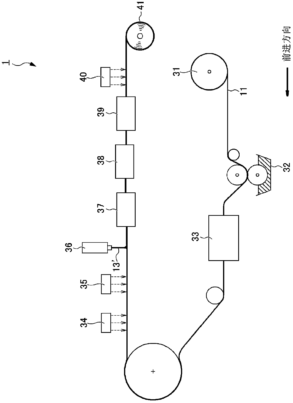
[0111] figure 1 It is a figure which shows the pattern retardation film suitable for the image display apparatus of 1st Embodiment of this invention. In the image display device of the first embodiment, in the vertical direction ( figure 1 The pixels on the continuous liquid crystal display panel in the left and right directions are corresponding directions) are alternately divided into right-eye pixels displaying right-eye images and left-eye pixels displaying left-eye images, respectively, through the right-eye images data and the left eye is driven with image data. As a result, the display screen of the image display device is alternately divided into a strip area displaying an image for the right eye and a strip area displaying an image for the left eye, and simultaneously displays the image for the right eye and the image for the left eye. In this image display device, a patterned retardation film 1 is arranged on the panel surface (the viewer's side surfac...

Embodiment 1-1

[0220] As a base material, a 40 μm (refractive index: 1.48) acrylic film with an anti-glare treatment was used on the surface, and a photo-alignment layer composition was applied on the back side by a die coating method so that the film thickness after curing was 200 nm. This photo-alignment layer composition is to have the photo-alignment material 100 mass parts of polyvinyl alcohol cinnamate (PVCi) group and the epoxy monomer of refractive index 1.70 (the epoxy monomer with the difunctional group of fluorene skeleton, Trade name: OGSOL CG-500, Osaka Gas Chemical (Japanese: Osaka Gas Chemical)) 3.0 parts by mass were dissolved in a mixed solvent containing isobutyl acetate and the solids accounted for 5%. Thereafter, the composition was dried for 2 minutes in a dryer adjusted to 100° C. to evaporate the solvent and heat-cure the composition to form a photo-alignment layer (refractive index: 1.57).

[0221] Next, this photo-alignment layer was irradiated with a cumulative ligh...

Embodiment 1-2

[0224] A retardation film was obtained in the same manner as in Example 1-1, except that the same epoxy monomer as in Example 1-1 was contained at a ratio of 5.0 parts by mass with respect to 100 parts by mass of the photo-alignment material.


PUM

PropertyMeasurementUnit
hazeaaaaaaaaaa
roughnessaaaaaaaaaa
visible light transmittanceaaaaaaaaaa

Abstract

A retardation film capable of effectively suppressing interference fringes generated due to the difference in refractive index between a retardation layer and a pattern alignment layer while maintaining orientation. The retardation film (1) comprises: a substrate (11); an alignment layer (12) containing a photo-alignment material; and a retardation layer (13) containing a liquid crystal compound, wherein the alignment layer (12) is opposite to the alignment layer of the photo-alignment material The epoxy monomer is contained in the ratio of 3.0 mass parts or more and 8.0 mass parts or less per 100 mass parts.

Description

technical field [0001] The present invention relates to a retardation film including a substrate, an alignment layer, and a retardation layer having a liquid crystal compound, a method for producing the retardation film, an image display device using the retardation film, and the like. Background technique [0002] In recent years, flat panel displays capable of three-dimensional display have been proposed. Among them, in order to perform three-dimensional display on a flat panel display, it is generally necessary to selectively provide right-eye images and left-eye images to the viewer's right eye and left eye in a certain way. As a method of selectively providing an image for the right eye and an image for the left eye, for example, a passive method is known. The three-dimensional display method of the passive method will be described below with reference to the drawings. Figure 13 It is a schematic diagram showing an example of passive three-dimensional display using a ...

Claims


Application Information

Patent Timeline
Patent Type & Authority Patents(China)
IPC IPC(8): G02B5/30G02F1/13363G02B30/25
CPCB29D11/00644G02F2202/36G02B5/3016G02B5/3083G02B1/11G02F1/133631G02B30/27
Inventor 猪俣裕哉吉田亮平高坂洋介藤田贤治
Owner DAI NIPPON PRINTING CO LTD
Learn More