Method for controlling a hydrodynamic retarder that can be mechanically disengaged by a disconnect clutch
A separation clutch and hydraulic reducer technology, applied in the field of hydraulic reducer, can solve the problems of shortened service life and high separation clutch
- Summary
- Abstract
- Description
- Claims
- Application Information
AI Technical Summary
Problems solved by technology
Method used
Image
Examples
Embodiment Construction
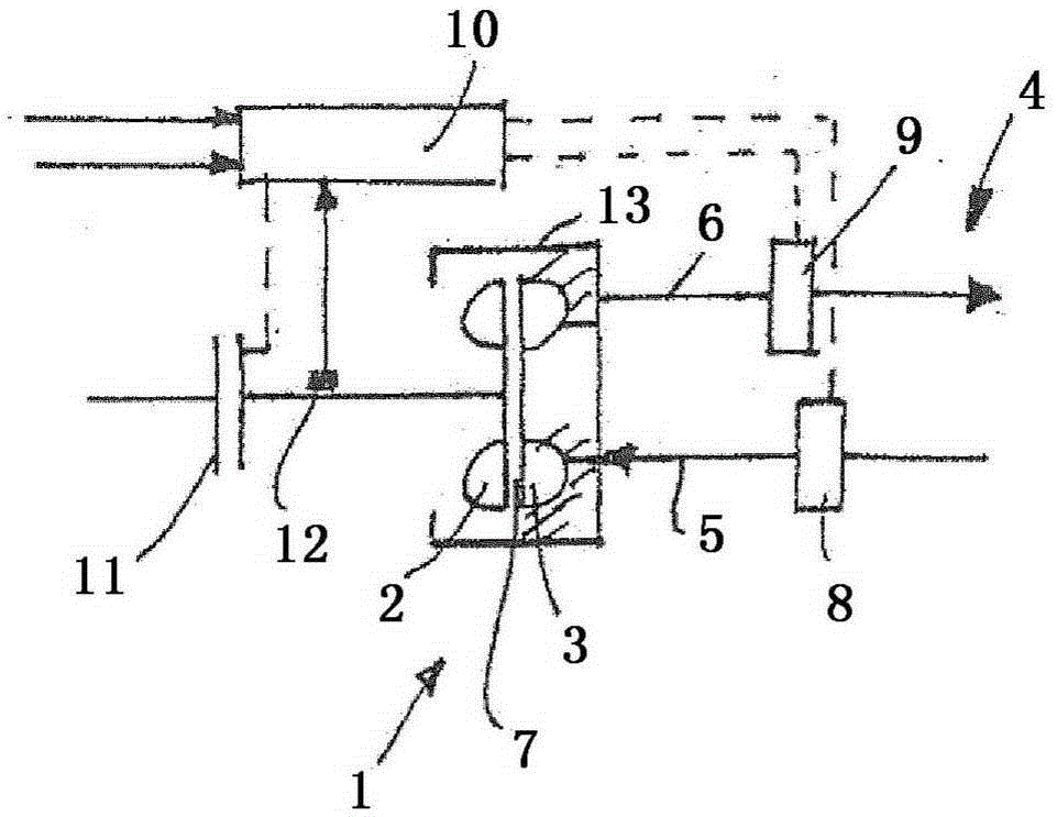
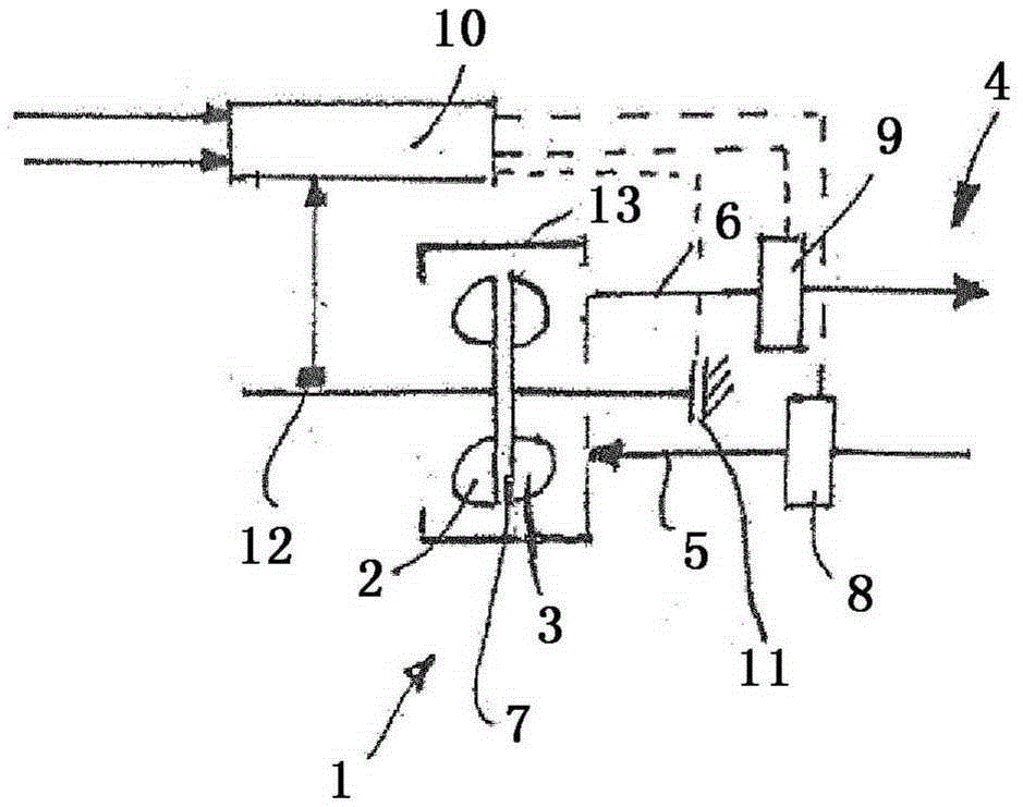
[0032] exist figure 1 A hydrodynamic retarder 1 with a rotor 2 and a stator 3 is shown in . Working medium is fed from the external working medium circuit 4 via the working medium supply 5 to the working chamber 7 and is discharged from the gear unit 1 via the working medium discharge 6 for cooling the working medium heated in the working chamber 7 . An inlet valve 8 is arranged in the working medium supply 5 , and a retarder outlet valve 9 is arranged in the working medium outlet 6 . The retarder control device 10 acts at least indirectly both on the retarder inlet valve 8 and also on the retarder outlet valve 9 . For the transition from non-braking operation to braking operation, the retarder inlet valve 8 is opened. The retarder outlet valve 9 is actuated with the set pressure such that it leads to the desired retention of the working medium and thus to the desired filling degree of the working chamber 7 . Alternatively, it is also conceivable to control the degree of fi...
PUM
 Abstract
Description
Claims
Application Information
 - R&D
- Intellectual Property
- Life Sciences
- Materials
- Tech Scout
- Unparalleled Data Quality
- Higher Quality Content
- 60% Fewer Hallucinations
Browse by: Latest US Patents, China's latest patents, Technical Efficacy Thesaurus, Application Domain, Technology Topic, Popular Technical Reports.
© 2025 PatSnap. All rights reserved.Legal|Privacy policy|Modern Slavery Act Transparency Statement|Sitemap|About US| Contact US: help@patsnap.com


