A two-stage non-isolated photovoltaic grid-connected inverter and its control method

A non-isolated, inverter technology, applied in photovoltaic power generation, control/regulation systems, instruments, etc.

Active Publication Date: 2017-11-14
HOHAI UNIV
View PDF4 Cites 0 Cited by
  • Summary
  • Abstract
  • Description
  • Claims
  • Application Information

AI Technical Summary

Problems solved by technology

However, this method requires two bus capacitor branches, and the withstand voltage of the second bus capacitor must be greater than the peak value of the grid voltage
On the other hand, the topology of the grid-connected inverter in this scheme is a traditional bridge inverter, so when using unipolar SPWM modulation, there is a problem of leakage current

Method used


Image

  • A two-stage non-isolated photovoltaic grid-connected inverter and its control method
  • A two-stage non-isolated photovoltaic grid-connected inverter and its control method
  • A two-stage non-isolated photovoltaic grid-connected inverter and its control method

Examples


Embodiment 1

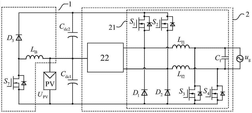
[0093] The two-stage non-isolated photovoltaic grid-connected inverter described in Embodiment 1 adopts the low-voltage power transmission branch 22 of the first structure, and the full-bridge power conversion circuit 2 includes six working modes:

[0094] Mode 1: the first power switch tube of the full-bridge power conversion circuit 2 S 1 , the fourth power switch tube S 4 and the fifth power switch tube S 5 turn on, the other power switch tubes in the full-bridge power conversion circuit 2 are turned off, and the incoming current flows through the first power switch tubes in sequence S 1 , the first filter inductor L f1 , power grid u g , the fourth power switch tube S 4 ; The bridge arm voltage of the full-bridge power conversion circuit 2 is the first DC bus capacitor C dc1 and the second DC link capacitor C dc2 sum of voltages.

[0095] Mode 2: the fifth power switch tube of the full-bridge power conversion circuit 2 S 5 and the fourth power switch tube...

Embodiment 2

[0131] The two-stage non-isolated photovoltaic grid-connected inverter described in Embodiment 2 adopts the low-voltage power transmission branch 22 of the first structure, and the full-bridge power conversion circuit 2 includes six working modes:

[0132] Mode 1: the first power switch tube of the full-bridge power conversion circuit 2 S 1 , the fourth power switch tube S 4 and the fifth power switch tube S 5 turn on, the other power switch tubes in the full-bridge power conversion circuit 2 are turned off, and the incoming current flows through the fourth power switch tube in sequence S 4 , power grid u g , the first filter inductor L f1 , the first power switch tube S 1 ; The bridge arm voltage of the full-bridge power conversion circuit 2 is the first DC bus capacitor C dc1 and the second DC link capacitor C dc2 sum of voltages.

[0133] Mode 2: the fifth power switch tube of the full-bridge power conversion circuit 2 S 5 and the fourth power switch tube ...


PUM


Abstract

The invention discloses a two-stage non-isolated photovoltaic grid-connected inverter, comprising a first DC bus capacitor, a second DC bus capacitor, a DC power conversion circuit, and a full-bridge power conversion circuit; the first DC bus The capacitors are sequentially connected to the photovoltaic module string and the input end of the DC power conversion circuit, the second DC bus capacitor is connected to the output end of the DC power conversion circuit, and the first DC bus capacitor is connected in series with the second DC bus capacitor to the full bridge The input end of the power conversion circuit and the output end of the full-bridge power conversion circuit are externally connected to a power grid, and a control method thereof is also disclosed. The invention reduces the capacitor voltage stress of the DC bus bar; only part of the power passes through the DC power conversion circuit, the number of power conversion stages is small, and the power loss is small; the dual step-down topology is adopted, there is no hidden danger of bridge arm direct connection, and the reliability is high; The diode freewheels, and the power switch tube can use MOSFET, which is beneficial to improve the conversion efficiency of the grid-connected inverter.

Description

technical field [0001] The invention relates to a two-stage non-isolated photovoltaic grid-connected inverter and a control method thereof, belonging to the technical field of power electronic converters. Background technique [0002] With the increasingly severe energy crisis and environmental pollution, new energy power generation technologies such as solar energy, wind energy, and fuel cells have become the focus of attention and research around the world. According to whether the new energy power generation system is connected to the public grid, it can be divided into two modes: grid-connected operation and independent operation. Among them, grid-connected operation is the most common way of new energy power generation application, and grid-connected inverter is a key component in the new energy grid-connected system, and it is of great significance to improve its conversion efficiency. [0003] In the traditional two-stage photovoltaic grid-connected inverter, the out...

Claims


Application Information

Patent Timeline
Patent Type & Authority Patents(China)
IPC IPC(8): H02M7/5387H02M3/155
CPCY02E10/56
Inventor 张犁吴红飞赵晋泉
Owner HOHAI UNIV
Why Eureka
Try Eureka