
Permanent magnet motor rotor with nonuniform-distribution magnetic poles

A permanent magnet motor, evenly distributed technology, applied in the direction of adjusting/balancing rotor, magnetic circuit rotating parts, manufacturing stator/rotor body, etc., can solve the problems of vibration and noise, affecting motor performance, motor torque fluctuation, etc. Achieve good performance in terms of back EMF harmonics, superior low-speed performance, and low vibration and noise.

Inactive Publication Date: 2016-01-20
SHANGHAI FINEPOWER TECH
View PDF10 Cites 3 Cited by
  • Summary
  • Abstract
  • Description
  • Claims
  • Application Information

AI Technical Summary

Problems solved by technology

[0003] However, the cogging torque will make the motor torque fluctuate and the speed fluctuate, so that the motor cannot run smoothly, affect the performance of the motor, and generate vibration and noise at the same time

Method used


Image

  • Permanent magnet motor rotor with nonuniform-distribution magnetic poles
  • Permanent magnet motor rotor with nonuniform-distribution magnetic poles
  • Permanent magnet motor rotor with nonuniform-distribution magnetic poles

Examples


Embodiment Construction

[0015] The present invention will be described in detail below in conjunction with the accompanying drawings.

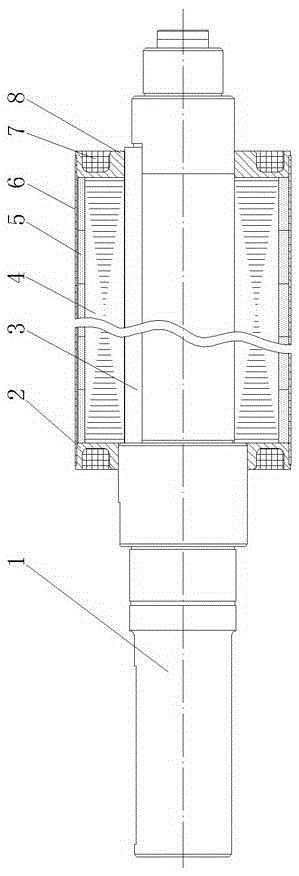
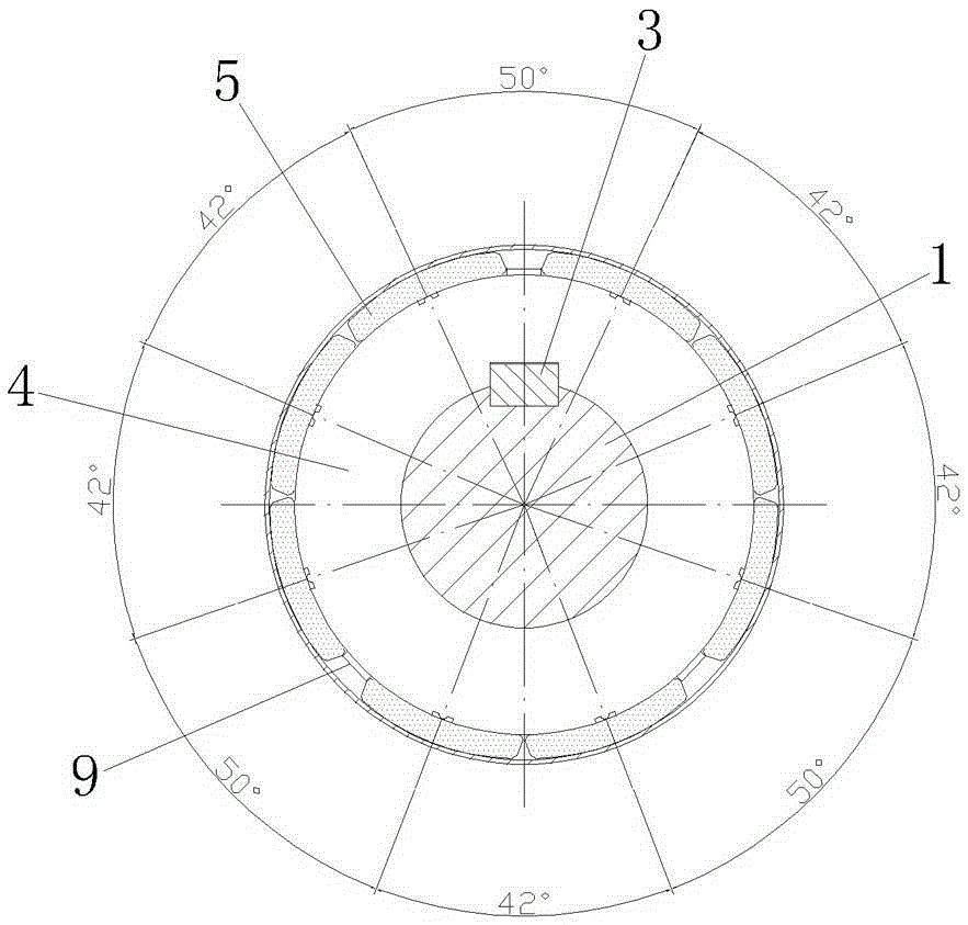
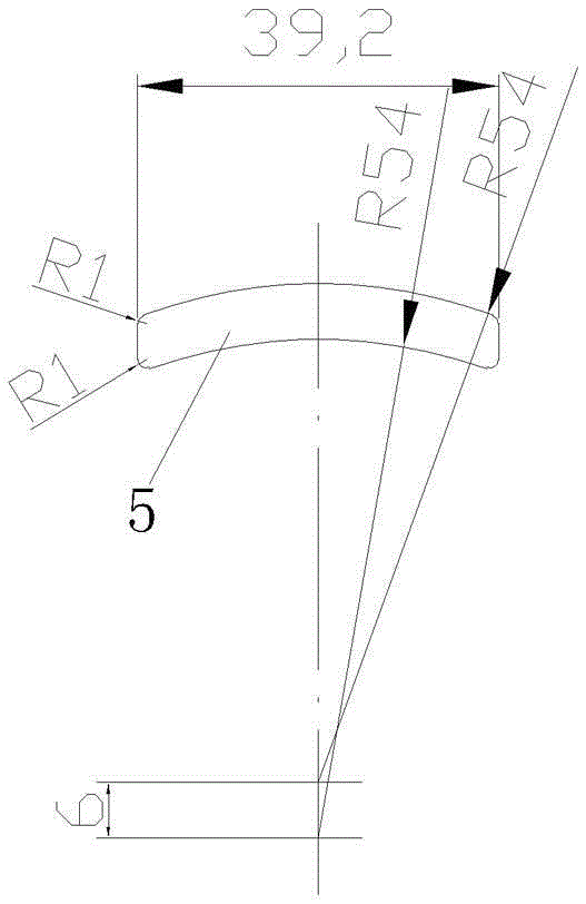
[0016] Such as figure 1 , figure 2 As shown, a permanent magnet motor rotor with non-uniform distribution of magnetic poles includes a rotating shaft 1, a rotor core 4, 8 magnetic poles 5, a first end fixing ring 2, a second end fixing ring 8, and a latitude-free belt 6. The rotor The iron core 4 is sleeved on the outside of the rotating shaft 1, the rotor core 4 is connected with the rotating shaft 1 through the key 3, the magnetic pole 5 is glued to the outer circumferential surface of the rotor core 4, and the rotating shaft 1 is respectively sleeved on the left and right ends of the rotor core 4 with first The end fixing ring 2, the second end fixing ring 8, and the non-weft tape 6 are wound on the surface of the magnetic pole 5, and the outer circumferential surface of the rotor core 4 is provided with three spacers 9 parallel to the rotation axis of the rotor...


PUM


Abstract

A permanent magnet motor rotor with nonuniform-distribution magnetic poles comprises a rotating shaft, a rotor iron core, 8 magnetic poles, a first end portion fixing ring, a second end portion fixing ring and a weftless band. The rotor iron core sleeves an outer side of the rotating shaft and the rotor iron core is connected to the rotating shaft through a key. The magnetic poles are cemented to an outer circumference surface of the rotor iron core. The first end portion fixing ring and the second end portion fixing ring sleeve left and right ends of the rotating shaft relative to the rotor iron core respectively. The weftless band winds a surface of the magnetic poles. The outer circumference surface of the rotor iron core is provided with three separation edges which are mutually parallel to a rotation axis of the rotor iron core. The three separation edges divide three gaps used for arranging the magnetic poles on the outer circumference surface of the rotor iron core. Three magnetic poles, three magnetic poles and two magnetic poles are arranged in the three gaps respectively. By using the motor rotor of the invention, a torque of a tooth groove can be reduced so that a vibration noise of the motor is small and operation is stable. Good performance on a counter electromotive force harmonic aspect is possessed. Simultaneously, low speed performance of the motor is superior, which is good for accurate speed and position control.

Description

technical field [0001] The invention relates to a permanent magnet motor rotor, in particular to a servo permanent magnet synchronous motor rotor. Background technique [0002] Cogging torque is an inherent phenomenon of permanent magnet motors. It is the torque generated in the circumferential direction by the magnetic field generated by the permanent magnets and the cogging of the armature core when the armature winding is not energized. Because the stator core of the servo motor is slotted, when the rotor rotates, the reluctance in the magnetic circuit changes, and cogging torque is generated. It is generated from the tangential force between the permanent magnet and the armature teeth, so that the rotor of the permanent magnet motor has a tendency to align with the stator along a certain direction, trying to position the rotor in certain positions, the cogging rotation Moment is an oscillating torque resulting from this tendency. [0003] However, the cogging torque wi...

Claims


Application Information

Patent Timeline
Patent Type & Authority Applications(China)
IPC IPC(8): H02K1/28H02K1/27H02K3/51H02K15/02H02K15/16
Inventor 桑立宁
Owner SHANGHAI FINEPOWER TECH
Learn More