
Optical fiber vibration detection system and optical fiber vibration detection method

A fiber optic vibration and detection system technology, applied in the direction of measuring devices, measuring ultrasonic/sonic/infrasonic waves, instruments, etc., can solve the problems of prolonging the detection distance and waste of resources, and achieve the goal of increasing the monitoring distance, solving the waste of resources, and improving the accuracy rate Effect

Active Publication Date: 2018-11-16
PIPECHINA SOUTH CHINA CO
View PDF10 Cites 1 Cited by
  • Summary
  • Abstract
  • Description
  • Claims
  • Application Information

AI Technical Summary

Problems solved by technology

[0004] By providing an optical fiber vibration detection system and an optical fiber vibration detection method, the present invention solves the technical problems of resource waste and limited effect of prolonging the detection distance in the prior art

Method used


Image

  • Optical fiber vibration detection system and optical fiber vibration detection method
  • Optical fiber vibration detection system and optical fiber vibration detection method
  • Optical fiber vibration detection system and optical fiber vibration detection method

Examples


Embodiment Construction

[0025] In order to make the objectives, technical solutions, and advantages of the embodiments of the present invention clearer, the technical solutions in the embodiments of the present invention will be described clearly and completely in conjunction with the accompanying drawings in the embodiments of the present invention. Obviously, the described embodiments It is a part of the embodiments of the present invention, not all the embodiments. Based on the embodiments of the present invention, all other embodiments obtained by those of ordinary skill in the art without creative work shall fall within the protection scope of the present invention.

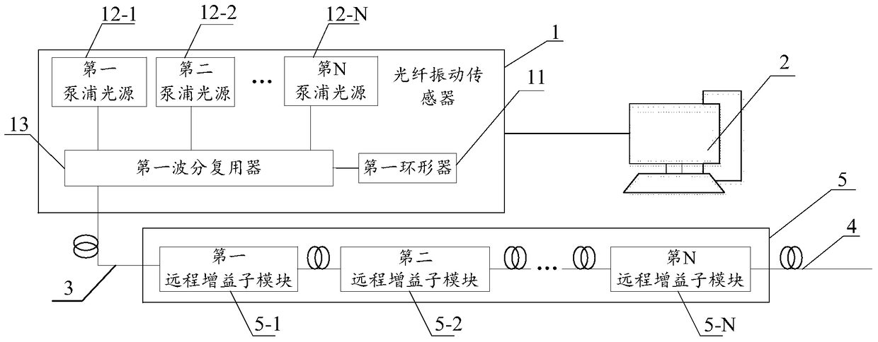
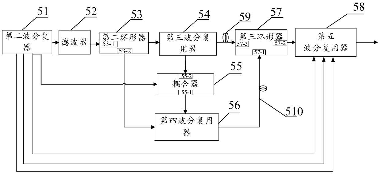
[0026] reference figure 1 As shown, an optical fiber vibration detection system provided by an embodiment of the present invention includes: a fiber vibration sensor 1, a host computer 2, a first sensing fiber 3, a second sensing fiber 4, and a remote gain module 5, where the fiber vibration The sensor 1 is connected to the host compu...


PUM


Abstract

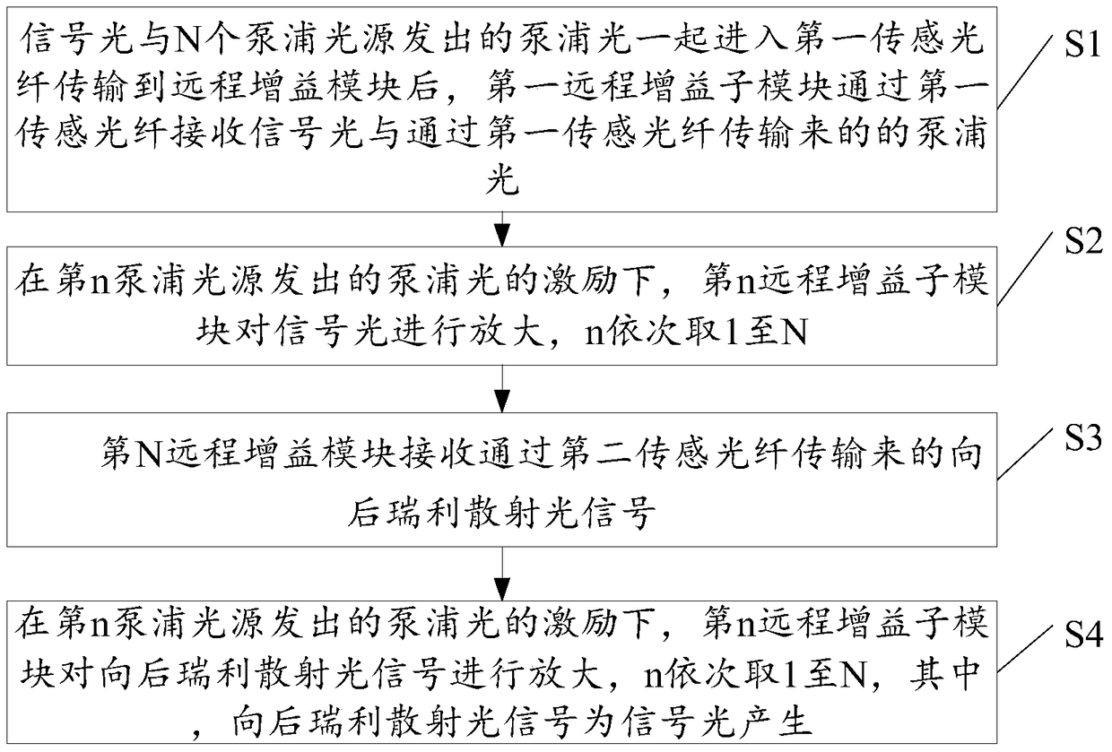
The invention discloses an optical fiber vibration detection system and an optical fiber vibration detection method. An optical fiber vibration sensor is connected with a host computer, the optical fiber vibration sensor comprises a first circulator, N pumping light sources, and a first wavelength division multiplexer, the first circulator is connected with the first wavelength division multiplexer, the N pumping light sources are connected with the first wavelength division multiplexer, the first wavelength division multiplexer is connected to a remote gain module via a first sensing optical fiber, and the remote gain module is also connected with a second sensing optical fiber. Signal light emitted by the first circulator and pumping light emitted by the N pumping light sources enter the remote gain module via the first wavelength division multiplexer, and the pumping light is downloaded via the remote gain module for the amplification of the signal light. Therefore, the technical problem that the actual production requirement cannot be satisfied due to limited detection distance of the optical fiber vibration signal detection system is solved, and the accuracy of remote optical fiber vibration detection is improved.

Description

Technical field [0001] The invention relates to the field of signal detection, in particular to an optical fiber vibration detection system and an optical fiber vibration detection method. Background technique [0002] Large-scale engineering structure health monitoring, oil pipeline protection, geological disaster prevention, etc. all need to collect vibration signals. Distributed optical fiber vibration sensors based on coherent Rayleigh technology (Φ-OTDR) have become a research hotspot due to the incomparable advantages of traditional sensors . At present, this technology is mainly used in fence intrusion detection, long-distance oil and gas pipeline detection, border security and other fields, and has achieved good application results. However, as the detection distance increases, the optical signal becomes very weak, especially for backward Rayleigh The scattered light signal becomes extremely weak, which brings great difficulties to signal detection. [0003] At present, i...

Claims


Application Information

Patent Timeline
Patent Type & Authority Patents(China)
IPC IPC(8): G01H9/00
Inventor 田孝忠周琰李金武孙巍王海明刘路王雪莉谭东杰邱红辉马云宾
Owner PIPECHINA SOUTH CHINA CO
Learn More