
Cone valve type dynamic visualization achieving device and method for high-pressure fuel oil system of diesel engine

A high-pressure fuel oil and diesel engine technology, applied in the direction of fuel injection devices, measuring devices, charging systems, etc., can solve the problems of reduction, valve shock vibration, lack of experimental basis and theoretical analysis, etc.

Active Publication Date: 2016-01-20
河北索奇汽车电子科技有限公司
View PDF5 Cites 9 Cited by
  • Summary
  • Abstract
  • Description
  • Claims
  • Application Information

AI Technical Summary

Problems solved by technology

However, as the injection pressure increases, the pressure of the fuel oil will drop sharply when it flows through the cone valve area of ​​the fuel system, and part of the liquid fuel gas will be vaporized, and a gas-liquid two-phase cavitation flow will appear, causing the valve to shock and vibrate. accuracy and even the performance of the entire fuel system
At this stage, there are few experimental studies on the cavitation flow inside the fuel system, and there is a lack of corresponding experimental basis and theoretical analysis.

Method used


Image

  • Cone valve type dynamic visualization achieving device and method for high-pressure fuel oil system of diesel engine
  • Cone valve type dynamic visualization achieving device and method for high-pressure fuel oil system of diesel engine

Examples


Embodiment Construction

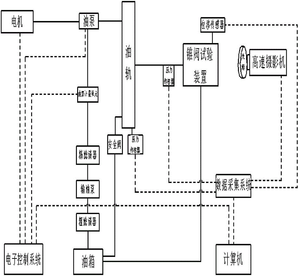
[0020] Such as figure 1 As shown, a schematic diagram of the realization method of the dynamic visualization device of the cone valve of the high-pressure fuel system of the diesel engine, including the electronic control system, the drive motor, the oil pump, the oil rail, the metering unit of the oil pump, the safety valve, the cone valve test device, the camera, the light source, the data Acquisition system and computer.

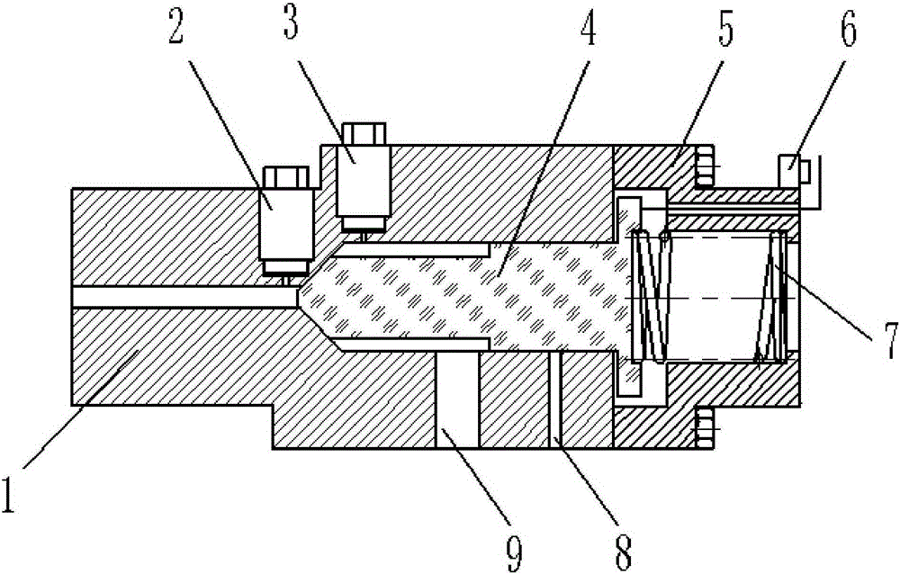
[0021] Such as figure 2 As shown, a device for realizing dynamic visualization of a cone valve in a high-pressure fuel system of a diesel engine, including a cone valve body (1), an inlet pressure sensor (2), an outlet pressure sensor (3), a valve core (4), and a compression cover (5) , displacement sensor (6), spring (7).

[0022] The cone valve body (1) is metal with a cone valve flow channel inside; the valve core (4) is made of optical glass and can move freely in the flow channel; the valve body (1) and valve core (4) The matching cone surface wi...


PUM


Abstract

The invention discloses a cone valve type dynamic visualization achieving device and method for a high-pressure fuel oil system of a diesel engine and belongs to the field of diesel engines. The cone valve type dynamic visualization achieving device is used for observing the flowing condition of fuel oil on a conical surface of a control valve and comprises a cone valve body, a pressure sensor, a valve element, a displacement sensor and a spring. Force borne by the valve element is changed to be balanced by regulating the pressure of an oil inlet of the cone valve body, so that the valve element is in the stable state again under the action of the spring, and the movement rule of the valve element and the change of a flow field in a flow channel are explored. By the adoption of the cone valve type dynamic visualization achieving device and method, measurement of cavitation flow parameters and observation of the development and change of bubbles can be conducted under a high pressure difference condition, and the dynamic change process of flowing of the fuel oil on the conical surface can be observed in real time.

Description

technical field [0001] The invention relates to a dynamic visualization device and method for a cone valve of a high-pressure fuel system of a diesel engine and belongs to the technical field of diesel engines. Background technique [0002] In order to meet the needs of fuel economy and adapt to strict emission regulations, the fuel system of contemporary diesel engines has been fully electronically controlled. At present, the electronically controlled fuel system is developing towards higher injection pressure and higher control accuracy. However, as the injection pressure increases, the pressure of the fuel oil will drop sharply when it flows through the cone valve area of ​​the fuel system, and part of the liquid fuel gas will be vaporized, and a gas-liquid two-phase cavitation flow will appear, causing the valve to shock and vibrate. accuracy and even the performance of the entire fuel system. At this stage, there are few experimental studies on the cavitation flow insi...

Claims


Application Information

Patent Timeline
IPC IPC(8): F02M65/00
Inventor 仇滔高壮雷艳
Owner 河北索奇汽车电子科技有限公司
Learn More