Resistance type crane safety device capable of preventing aslant pulling and hanging

A technology of safety devices and cranes, which is applied in the directions of safety devices, transportation and packaging, and load hanging components, etc., which can solve problems such as accidents, collisions with people or objects, and damage to rope arrangement devices, and achieve easy manufacturing, installation, use, and structure The effect of simple, good contact

Inactive Publication Date: 2016-01-20
HENAN SPECIAL EQUIP INSPECTION INST XINXIANG BRANCH
View PDF4 Cites 3 Cited by
  • Summary
  • Abstract
  • Description
  • Claims
  • Application Information

AI Technical Summary

Problems solved by technology

[0005] 1. Crooked pulling and inclined lifting will increase the load of the crane, which may cause serious overload of the mechanism and motor, reduce the service life of the crane, and even cause structural damage to the crane
[0006] 2. Crooked pulling and hanging will increase the wear of the wire rope, reel and pulley, and may damage the rope arrangement
[0007] 3. Crooked pulling and hanging may cause the wire rope to come out of the rope groove of the drum and be wound on the drum in multiple layers, and may also cause the wire rope to come out of the pulley groove, causing the wire rope to fall off the road.
[0008] 4. Slanted lifting will cause the load to generate lateral component force. Once the load is off the ground and loses the constraint of ground friction, it will swing along the direction of the horizontal component force, which may hit people or objects and cause accidents.

Method used


Image

  • Resistance type crane safety device capable of preventing aslant pulling and hanging
  • Resistance type crane safety device capable of preventing aslant pulling and hanging
  • Resistance type crane safety device capable of preventing aslant pulling and hanging

Examples


Embodiment Construction

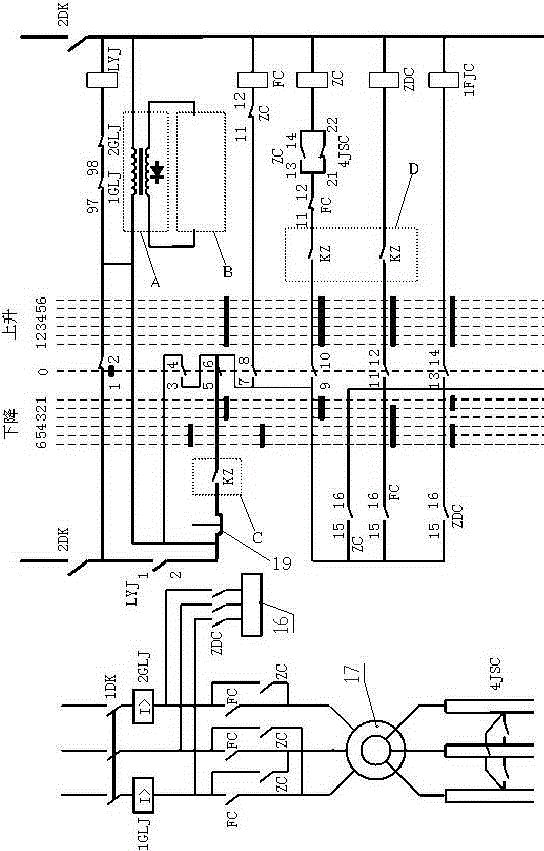
[0030] image 3 and Figure 4 Among them, 1DK is the power circuit switch; 2DK is the control circuit switch; 1GLJ and 2GLJ are overcurrent contactors; ZDC is the brake contactor; ZC is the rising direction contactor; FC is the falling direction contactor; Resistance contactor; FWL is a sliding rheostat mechanism formed by connecting wire 8, rheostat disc and sliding contact; KZ is a control contactor.

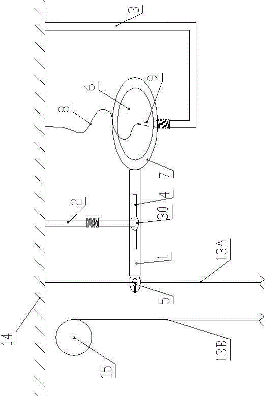
[0031] figure 1 Among them, the symbol 13A shows the hoisting wire rope on one side of the stationary end, and the symbol 13B is the hoisting wire rope on the other side.

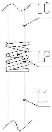
[0032] like figure 1 , figure 2 , image 3 , Figure 4 and Figure 5 As shown, the safety device of the resistance type crane of the present invention includes a slide bar 1, a guide bar 2 and a fixed bar 3, and the guide bar 2 and the fixed bar 3 are all welded to the hoisting mechanism 14 (such as being welded to the hoisting mechanism 14), the slide bar 1 is arranged horizontally and the middle ...


PUM


Abstract

The invention discloses a resistance type crane safety device capable of preventing aslant pulling and hanging. The safety device comprises a guiding rod, a fixing rod and a horizontally arranged sliding rod. A long hole is formed in the middle of the sliding rod in the length direction of the sliding rod, and the bottom end of the guiding rod is connected into the long hole in a sliding mode; a sliding hole is formed in one end of the sliding rod, and the other end of the sliding rod is fixedly connected with a resistance changing disc; a connection wire is connected to the center of an inner resistance disc; the bottom of the fixing rod is bent and then stretches to the position below the inner resistance disc, the bottom end of the fixing rod is bent upwards and then is provided with a big-end-down conical portion, a sliding contact is formed at the tip end of the conical portion, and the resistance changing disc is supported by the sliding contact in a sliding mode. When a hanging hook or other lifting appliances are located at normal hoisting positions, the center of the resistance changing disc makes contact with the sliding contact. The resistance type crane safety device is simple in structure and convenient to manufacture, mount and use; the safety device additionally mounted on an existing lifting device can prevent the aslant pulling and hanging phenomenon, and safe operation of a crane is guaranteed.

Description

technical field [0001] The invention relates to the technical field of cranes, in particular to the anti-skewing and inclined-hanging technology of cranes. Background technique [0002] In most existing cranes, there is a relatively static end of the hoisting wire rope, which does not move with the rotation of the drum or pulley, and is called the static end; for example, one end of the hoisting wire rope of many cranes is fixedly connected to the hoisting mechanism. The hoisting mechanism at this place is relatively static, and the other end of the hoisting wire rope goes around the movable pulley downwards and then turns back upwards to connect the reel or passes through the movable pulley block and the fixed pulley (group) to connect the reel. In the existing few cranes, there is no fixed end of the hoisting wire rope, and the present invention does not relate to this type of crane. The hoisting wire rope of the crane is connected with a hook or other types of spreaders ...

Claims


Application Information

Patent Timeline
Patent Type & Authority Applications(China)
IPC IPC(8): B66C15/00
Inventor 董文常岚秦文明王锡征孙庆国
Owner HENAN SPECIAL EQUIP INSPECTION INST XINXIANG BRANCH
Why Eureka
Try Eureka