High-voltage suspension type MOSFET/IGBT continuous grid driving circuit

A gate drive circuit and drive circuit technology, applied in electrical components, excitation or armature current control, output power conversion devices, etc., can solve problems such as power amplification, limit the application range of power drive circuits, etc. Easy to debug effects

Inactive Publication Date: 2016-01-13
NO 43 INST OF CHINA ELECTRONICS TECH GRP CETC
View PDF4 Cites 1 Cited by
  • Summary
  • Abstract
  • Description
  • Claims
  • Application Information

AI Technical Summary

Problems solved by technology

[0003] The DC motor drive circuit is mainly composed of a pulse width modulation circuit, a drive circuit, and an H-bridge amplifier circuit. The pulse width modulation circuit completes the modulation of the input error signal and the triangular wave carrier signal, and generates an output width-modulated square wave signal. The drive circuit completes the distribution of the drive signal. and processing, the H-bridge circuit completes the power amplification; the current high-voltage drive circuits mainly include special integrated drive circuits provided by foreign companies such as IR, such as IR2110, IR2130, etc. The high-end drive power and ground of these special integrated drive circuits are in a suspended state. There is a problem that when the input signal of the drive circuit is a DC signal, the high-end MOSFET / IGBT of the H-bridge circuit has no output. In practical applications, it is mainly to limit the duty cycle of the input signal of the drive circuit to between 5% and 95%, but this cannot Meet the continuous gate drive requirements of MOSFET / IGBT in the range of duty cycle from 0 to 1, which limits the application range of power drive circuits; therefore, it is necessary to increase the continuous gate drive circuit of MOSFET / IGBT to improve the shortcomings of the above-mentioned drive circuit applications
[0004] Currently, the MOSFET / IGBT continuous gate drive circuit implementation shown is usually a charge pump type circuit, such as figure 1 As shown, the circuit includes a charging circuit 1, a charging circuit 2 and a square wave resonant circuit 3. When the circuit works at 100% duty cycle signal input, the square wave resonant circuit 3 generates a square wave signal with a certain frequency. When the square wave When the signal is at a low level, the power supply + VS charges the energy storage capacitor C10 through V5. When the square wave signal is at a high level, C10 charges the bootstrap capacitor C9 through V4 to maintain the energy of the bootstrap capacitor, and finally the circuit operates at 100 When the % duty ratio input signal, the H bridge outputs a 100% duty ratio signal to ensure the continuity of the output current; the charge pump circuit realizes the continuous gate drive of MOSFET / IGBT, but the continuous gate drive circuit requires the H bridge to be low The end tube V10 is turned on first to charge C9, that is, the drive circuit must first work in a square wave signal, and then enter the DC input to ensure continuous gate drive function. This is a major defect of the charge pump circuit

Method used


Image

  • High-voltage suspension type MOSFET/IGBT continuous grid driving circuit
  • High-voltage suspension type MOSFET/IGBT continuous grid driving circuit

Examples


Embodiment Construction

[0014] The present invention will be further explained below in conjunction with the drawings:

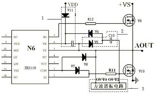
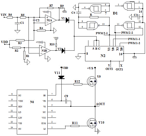
[0015] Such as figure 2 As shown, the high-voltage floating MOSFET / IGBT continuous gate drive circuit of this embodiment includes a square wave resonant circuit 3, a charging circuit 1, an amplitude discriminating circuit 4, and a channel switching circuit 2. The amplitude discriminating circuit 4 is used to discriminate the input signal State, to provide a switch control signal for the channel switching circuit 2. When the input signal is in the linear region, it outputs a low-level signal, and when the input signal is outside the linear region, it outputs a high-level signal; the channel switching circuit 2 is used to identify according to the amplitude The output switch control signal of the circuit 4 switches the input signal channel of the drive circuit. When the amplitude discrimination circuit 4 outputs a low-level signal, it outputs a normal widened square wave signal to the ...


PUM


Abstract

The invention relates to a high-voltage suspension type MOSFET / IGBT continuous grid driving circuit, which comprises a square wave resonance circuit, a charging circuit, an amplitude discrimination circuit and a channel switching circuit, wherein the amplitude discrimination circuit is used for discriminating the state of an input signal, providing a switching control signal for the channel switching circuit, outputs a low-level signal when the input signal is in a linear region, otherwise outputs a high-level signal when the input signal is outside the linear region; and the channel switching circuit is used for switching input signal channels of the driving circuit according to the switching control signal output by the amplitude discrimination circuit, outputs a normal width modulation square wave signal to the driving circuit when the amplitude discrimination circuit outputs the low-level signal, otherwise outputs a resonance square wave signal to the driving circuit when the amplitude discrimination circuit outputs the high-level signal. The high-voltage suspension type MOSFET / IGBT continuous grid driving circuit is simple in structure and convenient in debugging, has no requirements on initial working conditions, makes continuous grid driving more reliable and effective, and satisfies the engineering application of various types.

Description

Technical field [0001] The invention relates to the technical field of direct current motor driving, in particular to a high-voltage floating MOSFET / IGBT continuous gate driving circuit. Background technique [0002] The DC motor drive circuit is the core unit of the servo system. It mainly completes the power drive and speed regulation of the motor. It can be widely used in military fields such as aerospace, aviation, ships, weapons, electronics, and electric vehicles, robots, drones, wind power, Industrial applications such as solar power generation. [0003] The DC motor drive circuit is mainly composed of a pulse width modulation circuit, a drive circuit, and an H-bridge amplifier circuit. The pulse width modulation circuit completes the modulation of the input error signal and the triangular wave carrier signal to generate an output width-modulated square wave signal, and the drive circuit completes the distribution of the drive signal The H-bridge circuit completes the power...

Claims


Application Information

Patent Timeline
IPC IPC(8): H02P7/28H02M1/088
Inventor 周敛荣王海涛李彩侠潘美珍
Owner NO 43 INST OF CHINA ELECTRONICS TECH GRP CETC
Why Eureka
Try Eureka