
DVOR (Doppler Vor) omnidirectional range reflective net antenna damping system

An omnidirectional beacon and shock absorption system technology, applied in the direction of antenna support/installation device, etc., can solve the problems of reflective nets, high track stiffness, affecting antenna signal accuracy, large vibration frequency and amplitude, etc., and achieve shock isolation performance Good, wide application range, reducing the effect of vibration frequency and amplitude

Active Publication Date: 2016-01-13
HENGSHUI TONGGUANG TOWER IND
View PDF8 Cites 2 Cited by
  • Summary
  • Abstract
  • Description
  • Claims
  • Application Information

AI Technical Summary

Problems solved by technology

[0017] 1) The track is directly connected to the mesh, and trampling during construction or maintenance is likely to have a certain impact on the antenna track, causing shaking and displacement of the antenna, and affecting the accuracy of the antenna signal;
[0018] 2) In order to meet the requirements of urban planning and development, the height of the reflection net is built higher and higher, and extreme weather occurs from time to time, causing unprecedented pressure on the fixing of the antenna equipment of the reflection net. Due to the lack of effective seismic isolation measures, coupled with reflection nets, tracks, etc. The average stiffness is very large, causing a large vibration frequency and amplitude, while the existing antenna equipment requires that the vibration frequency should be less than 2HZ, and the amplitude should be less than 1 degree, which seriously affects the equipment signal and poses a challenge to aircraft navigation in bad weather.

Method used


Image

  • DVOR (Doppler Vor) omnidirectional range reflective net antenna damping system
  • DVOR (Doppler Vor) omnidirectional range reflective net antenna damping system
  • DVOR (Doppler Vor) omnidirectional range reflective net antenna damping system

Examples


Embodiment Construction

[0048] The principles and features of the present invention are described below in conjunction with the accompanying drawings, and the examples given are only used to explain the present invention, and are not intended to limit the scope of the present invention.

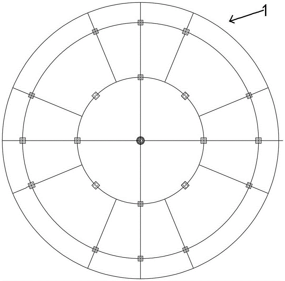
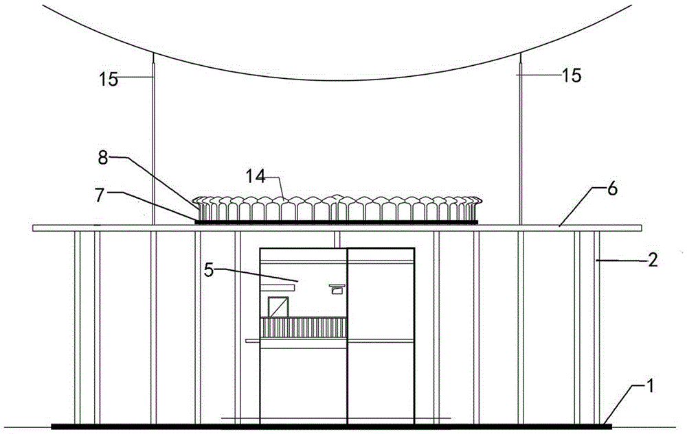
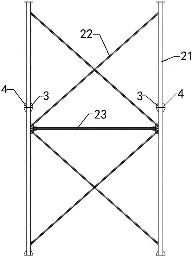
[0049] Such as figure 1 and 2 , a DVOR omnidirectional beacon reflective net antenna damping system, wherein the omnidirectional beacon reflective net comprises a reflective net base 1, a reflective net support 2, a reflective net 6, an antenna track 7, an antenna support 8 and The antenna array 14 and the communication room 5 are set in the middle of the reflective net support 2 under the reflective net. In addition, auxiliary facilities such as lightning rods 11 are also provided at the four corners of the reflective net. The layout of the reflective net foundation 1 is as follows: figure 1 , arranged in a circular inner and outer layers, the reflective net support 2 is composed of pillars 21, cross bars 23 and d...


PUM


Abstract

The invention discloses a DVOR (Doppler Vor) omnidirectional range reflective net antenna damping system. A damping support I is arranged between an upper strut and a lower strut of a reflective net bracket, a damping support II is arranged between a reflective net and an antenna orbit, and the two damping supports are high-damping rubber gaskets with built-in gasket lined steel plates. The system is reasonable in design and convenient to install, and is easy to replace when the rubber is aged after installation; the damping support I is arranged between a steel girder and the orbit, so that contact between meshes and the orbit is radically avoided, and the trample problem during overhauling or construction is solved; the damping supports serving as dampers consume energy inside, thus effectively counteracting the influence of wind load on an orbit antenna under severe weather and reducing the vibration frequency and times of the antenna orbit; the antenna orbit is effectively separated from the reflective net steel girder, thus avoiding resonance caused by the same frequency with the reflective net; and the damping support II prolongs the natural vibration period of the structure and reduces the vibration frequency of the structure without influencing the structural strength.

Description

technical field [0001] The invention relates to an antenna device for receiving and reflecting aircraft signals in a civil aviation system, in particular to a DVOR omnidirectional beacon reflection network antenna shock absorption system. Background technique [0002] The DVOR omnidirectional beacon reflection network is an antenna device that is indispensable for receiving and reflecting aircraft signals in conjunction with the launch equipment in the civil aviation system. It is generally built near the outside of the airport runway and on each navigation platform on the flight route, with a distance of about 300 kilometers. It is used to provide accurate position navigation information for aircraft on take-off and on the route. It works in the VHF band and uses the Doppler principle to provide the magnetic orientation information of the aircraft equipped with corresponding equipment relative to the ground equipment. [0003] The existing DVOR omnidirectional beacon reflec...

Claims


Application Information

Patent Timeline
Patent Type & Authority Applications(China)
IPC IPC(8): H01Q1/18
Inventor 贾国栋
Owner HENGSHUI TONGGUANG TOWER IND
Learn More