A photoconductive detector

A detector and photoconductive technology, applied in the field of detectors, can solve the problems of reduced quantum efficiency of detectors, complex electrode structure, weakened current signal, etc. than the improved effect

Inactive Publication Date: 2017-08-15
CHONGQING UNIV
View PDF5 Cites 0 Cited by
  • Summary
  • Abstract
  • Description
  • Claims
  • Application Information

AI Technical Summary

Problems solved by technology

[0005] Although the above two electrode structures that enhance single-carrier collection performance can improve the energy resolution of the detector, the overall quantum efficiency of the detector will be reduced due to the weakening of the current signal in a considerable area near the cathode.
And due to the addition of new electrodes, the electrode structure becomes more complex

Method used


Image

  • A photoconductive detector
  • A photoconductive detector
  • A photoconductive detector

Examples


Embodiment Construction

[0026] The present invention will be further described below in conjunction with the accompanying drawings and embodiments.

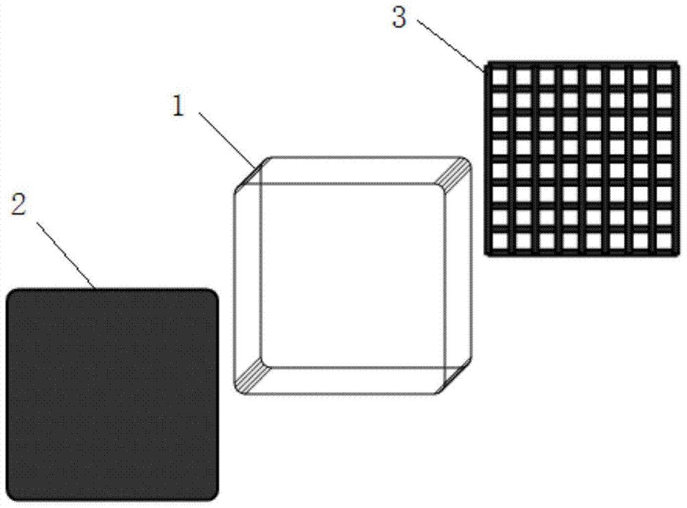
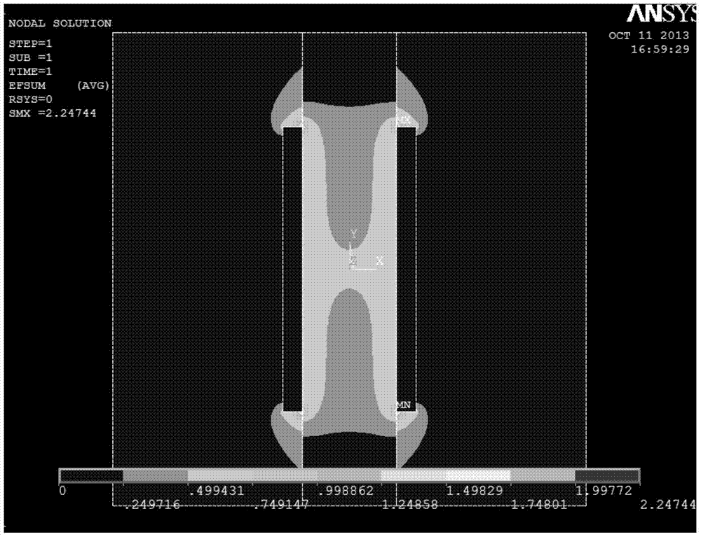
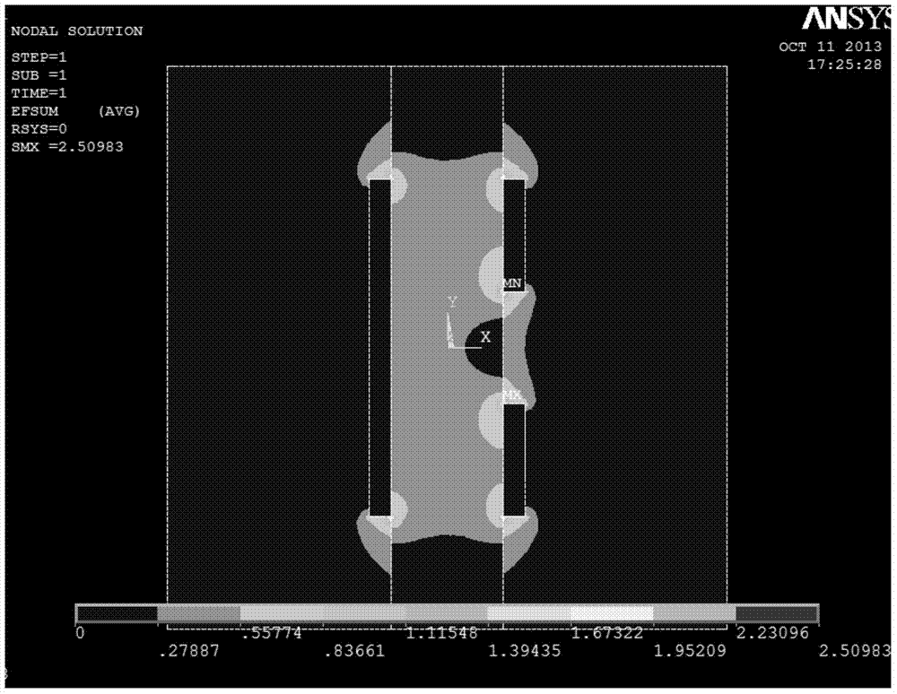
[0027] A photoconductive detector, such as figure 1 As shown, it includes a semiconductor 1 and two electrodes located on both sides of the semiconductor 1, the cathode 2 is a flat plate in the prior art, and the anode 3 is different from the cathode 2 in that it has a plurality of through holes uniformly distributed along the longitudinal direction of the detector electric field , so that the anode 3 is a network-like or mesh-shaped electrode plate, thereby reducing the effective area of ​​the anode 3, and enhancing the electric field near the anode 3, so that the electric field inside the detector tends to be uniform in the lateral direction, and the anode The weight field near 3 has been strengthened. The electric field distribution of the detector is as figure 2 and image 3 as shown, figure 2 is the electric field distribution of detectors us...


PUM


Abstract

The invention relates to a photoconductive detector, which comprises a semiconductor, and a cathode and an anode located at two sides of the semiconductor, wherein the cathode is a plate-type cathode, and the anode is provided with multiple uniformly-distributed through hole. The axial direction of the through holes is along the longitudinal direction of an electric field, the electric field inside the detector thus tends to homogenization, and a weight field near the anode is enhanced. The quantum efficiency of the detector is not reduced significantly while the energy resolution of the detector is improved.

Description

technical field [0001] The invention relates to a detector, in particular to a photoconductive detector. Background technique [0002] Semiconductor nuclear radiation detectors usually use metal-semiconductor-metal (MSM) photoconductive detectors, that is, two flat-plate contact electrodes are made at both ends of a high-resistance semiconductor, thus forming a so-called flat-panel detector. The main advantages of this detector are simple electrode structure, large acceptance angle and capture volume for photons or particles, and high capture efficiency. However, its disadvantage is that due to the difference in electron and hole transport properties, the electron drift speed is fast and the life is long, while the hole drift speed is slow and the life is short, so the collection depth of the electron charge is much higher than the collection depth of the hole charge, thus The hole collection efficiency near the anode is greatly reduced, so that the charge collection effici...

Claims


Application Information

Patent Timeline
Patent Type & Authority Patents(China)
IPC IPC(8): H01L31/0224H01L31/09
CPCH01L31/0224H01L31/09
Inventor 张流强
Owner CHONGQING UNIV
Why Eureka
Try Eureka