
System and method for grounding wire monitoring

A monitoring system and grounding wire technology, which is applied in the field of power lines, can solve problems such as difficulty in popularization, damage to the grounding wire, and inability to judge the working status by itself.

Active Publication Date: 2017-10-20
BEIJING YOUFUTE TECH
View PDF5 Cites 0 Cited by
  • Summary
  • Abstract
  • Description
  • Claims
  • Application Information

AI Technical Summary

Problems solved by technology

[0004] The existing grounding wire monitoring system has the following defects and deficiencies: 1. It is necessary to install a grounding body, set up a ground wire pile and a fixed RFID, the workload on site is heavy, and the probability of being damaged by man-made or natural outsiders increases
2. It is not possible to flexibly hang / remove the ground wire at any position required by the project
3. It is necessary to disconnect the conductor of the grounding wire, resulting in an obvious disconnection point in the grounding wire, which will easily increase the number of fault points and damage the grounding wire
4. Large size, embedded with independent GPS and GPRS modules
5. High energy consumption, frequent charging, complicated operation and maintenance
6. Using the RFID combination judgment section, the on-site equipment cannot judge the working status by itself, and needs to be processed by the background server, which easily leads to a high probability of misjudgment
7. GIS support is required, the workload of the database is heavy in the early stage, and the work is limited
At present, it is difficult to popularize and promote GIS in most (prefectural) county-level power system enterprises in my country.
[0008] To sum up, in the existing technology, there are potential accidents in the supervision of grounding wires, such as false grounding wires hanging indiscriminately, and random distribution points, which cannot achieve real-time monitoring

Method used


Image

  • System and method for grounding wire monitoring
  • System and method for grounding wire monitoring
  • System and method for grounding wire monitoring

Examples


Embodiment Construction

[0042] The principles and features of the present invention are described below in conjunction with the accompanying drawings, and the examples given are only used to explain the present invention, and are not intended to limit the scope of the present invention.

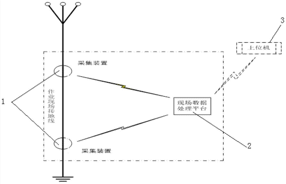
[0043] Such as figure 1 As shown, it is a grounding wire supervision system of the present invention, which includes two acquisition devices 1 arranged on the same ground wire and separated by a certain distance, an on-site data processing platform 2 and a host computer 3, and the two acquisition devices 1 and the host computer 3 are both It is connected with the on-site data processing platform 2, and the distance between the two acquisition devices 1 on the grounding line is 5m-6m.

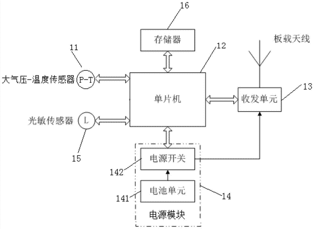
[0044] Two collection devices 1 are used to collect data containing atmospheric pressure and temperature values ​​according to the sampling period, and calculate the actual height value, and send the data packet containing the actual ...


PUM


Abstract

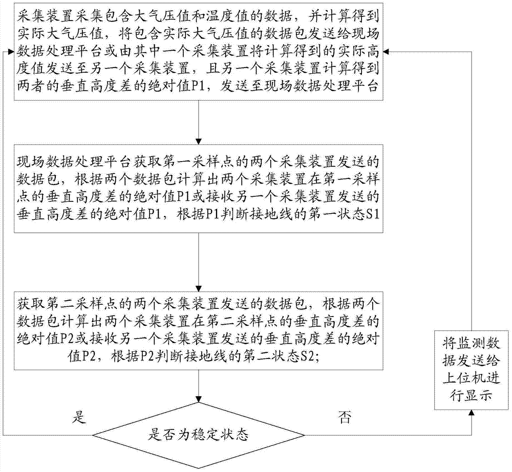
The invention relates to a ground wire supervision system and method. The system comprises two acquisition devices arranged at different positions of a ground wire, an onsite data processing platform and a host computer. The two acquisition devices are connected with the host computer and the onsite data processing platform; the two acquisition devices acquire data including atmosphere pressure values and temperature values according to a sampling period, calculate actual height values and send the data including the actual height values to the onsite data processing platform or absolute values of vertical height differences are calculated by one of the acquisition devices; and the onsite data processing platform, according to data packets, which include the actual height values, of a first sampling point and a second sampling point, respectively calculates vertical height difference absolute values P1 and P2 or receives the vertical height difference absolute values P1 and P2, according to the P1 and the P2, determines the state of the ground wire, determines whether the ground wire is stable, and if not, sends monitoring data to the host computer for display. According to the invention, the state of the ground wire in a power operation field can be monitored in real time.

Description

technical field [0001] The invention relates to the technical field of power lines, in particular to a grounding wire supervision system and method. Background technique [0002] In the power system, the grounding wire is called a life-saving wire. Reasonable connection and detachment of grounding wires is the primary condition for ensuring the safety of personnel and equipment at various job sites, and it is also a safety measure that leaders at all levels in the power sector and on-site safety supervisors are most concerned about. Due to technical development, management methods and personnel responsibility, the traditional extensive control method has been used for many years, resulting in the following results: 1. The maintenance of the grounding wire is not in place, resulting in the "sick" operation of the grounding wire. It can't play the role of "life-saving line"; 2. Individual personnel are eager to operate conveniently, hang up at will, and sometimes even hang up...

Claims


Application Information

Patent Timeline
Patent Type & Authority Patents(China)
IPC IPC(8): G05B19/042
CPCG05B19/0428G05B2219/24215
Inventor 焦治宁柳晖
Owner BEIJING YOUFUTE TECH
Learn More