Overload-resistant capacitive triaxial MEMS accelerometer

An accelerometer, capacitive technology, applied in the measurement of acceleration, multi-dimensional acceleration measurement, speed/acceleration/shock measurement, etc., can solve the problems of increasing manufacturing cost, accelerometer not working, measurement inaccurate, etc., to avoid high overload shock , the mode shape is stable, and the effect of increasing the natural frequency

Inactive Publication Date: 2016-01-13
EAST CHINA INST OF OPTOELECTRONICS INTEGRATEDDEVICE
View PDF10 Cites 8 Cited by
  • Summary
  • Abstract
  • Description
  • Claims
  • Application Information

AI Technical Summary

Problems solved by technology

In the patent document "A Piezoresistive MEMS High Overload Accelerometer" (publication number CN103969467A), the piezoresistive principle can be used to achieve an overload shock exceeding 200,000g acceleration, but the accelerometer with this structure is usually used as a shell fuze switch. That is, the accelerometer only has a signal output when the impact reaches 200000g. When the normal acceleration value is small, the output signal is small, and the accelerometer basically does not work. At the same time, the accelerometer of this structure is limited to the acceleration movement in the XY plane. The structure and impact are not analyzed and evaluated
[0005] In the patent document "High Overload Three Degrees of Freedom Accelerometer" (publication number CN1667420A), the structure of the three degrees of freedom accelerometer adopts the principle of piezoresistive detection. However, when the acceleration is small, the displacement of the mass block is very small, the cantilever beam is not easy to deform, and the varistor value changes very little, resulting in low detection accuracy and inaccurate measurement. The shaft-plus-meter structure chips are manufactured separately and then uniformly mounted, which increases the manufacturing cost

Method used


Image

  • Overload-resistant capacitive triaxial MEMS accelerometer
  • Overload-resistant capacitive triaxial MEMS accelerometer
  • Overload-resistant capacitive triaxial MEMS accelerometer

Examples


Embodiment Construction

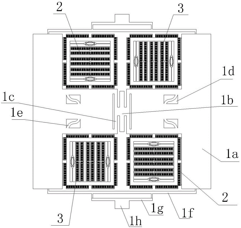
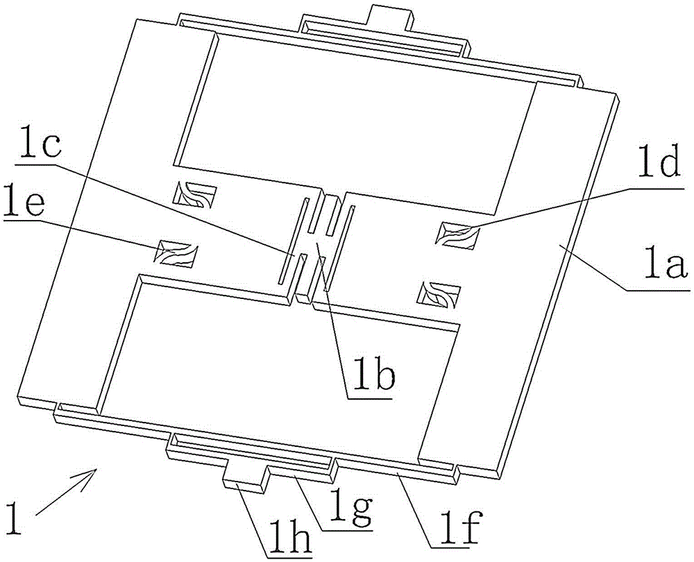
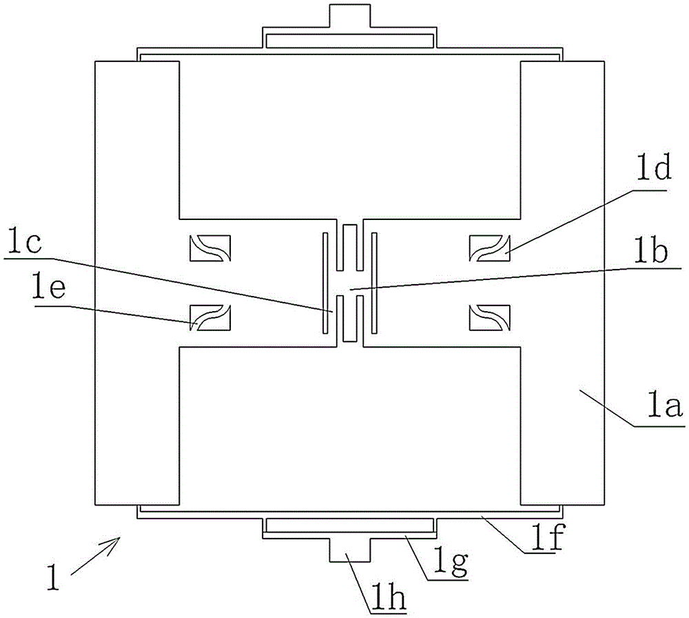
[0023] to combine Figure 1~3 As shown, the present invention provides an anti-overload capacitive three-axis MEMS accelerometer, including an X-axis detection unit 2, a Y-axis detection unit 3, and a Z-axis detection unit 1 disposed on a substrate;

[0024] The Z-axis detection unit 1 includes an H-shaped Z-axis mass block 1a, and the middle part of the Z-axis mass block 1a is provided with a Z-axis anchor body 1b and a Z-axis elastic beam 1c, and the Z-axis mass block 1a The two opening sides of the Z axis are respectively provided with mutually symmetrical Z-axis stress release beams, and each Z-axis stress release beam includes a first-level stress release beam 1f and a second-level stress release beam 1g in the shape of "冂", and a second-level stress release beam 1g. The stress release beam 1g spans the two ends corresponding to the opening side, and the primary stress release beam 1f is arranged in the middle outside the secondary stress release beam 1g; the length of th...


PUM


Abstract

The invention discloses an overload-resistant capacitive triaxial MEMS accelerometer. The accelerometer comprises an X axial direction detection unit, a Y axial direction detection unit and a Z axial direction detection unit. The X axial direction detection unit, the Y axial direction detection unit and the Z axial direction detection unit are provided with an X axial direction stress release beam, a Y axial direction stress release beam and a Z axial direction stress release beam respectively. The X axial direction stress release beam and the Y axial direction stress release beam are both beams shaped like a Chinese character kou, and are disposed on respective elastic beams respectively. The Z axial direction stress release beam includes a stress release beam with two grades shaped like a Chinese character jiong, and is disposed at an opening side of a Z axis mass block. Stress concentration areas are expanded from connections of all respective anchor points and all the axial elastic beams to the whole elastic beams, so the stress in the stress concentration areas can be effectively shared. The accelerometer is prevented from being impacted by excessively high overloads, can work normally in a high overload condition, is improved in inherent frequency, and has a more stable vibration mode.

Description

technical field [0001] The invention relates to the field of micro-electromechanical devices, in particular to an anti-overload capacitive three-axis MEMS accelerometer. Background technique [0002] MEMS accelerometers are an important part of microelectromechanical systems. Micro-electromechanical accelerometers are widely used as the core components of MIMUs due to their small size, low power consumption, easy integration, strong overload resistance and mass production. With the development of MEMS design methods and process technology, micro-mechanical accelerometers have been widely used in various consumer fields such as missile guidance, household appliances, and automotive electronics. [0003] Usually, the multi-axis capacitive accelerometer structure needs to install three accelerometer structures, which increases the cost of the chip and requires high installation accuracy. The three-axis integrated accelerometer has the problems of axial interference and lineari...

Claims


Application Information

Patent Timeline
Patent Type & Authority Applications(China)
IPC IPC(8): G01P15/18G01P15/125
Inventor 段宝明郭群英黄斌何凯旋陈璞王鹏
Owner EAST CHINA INST OF OPTOELECTRONICS INTEGRATEDDEVICE
Why Eureka
Try Eureka