
Production process for liquid accumulator

A production process and liquid storage technology, which is applied in the production process of liquid storage, can solve the problems that the refrigerant cannot be completely vaporized, affects the service life of the liquid storage, and the joint of the liquid storage is weak, etc., so as to achieve good sealing , flexible use and high liquid discharge efficiency

Active Publication Date: 2016-01-13
WUHU SANHUA REFRIGERATION FITTINGS
View PDF6 Cites 4 Cited by
  • Summary
  • Abstract
  • Description
  • Claims
  • Application Information

AI Technical Summary

Problems solved by technology

[0002] The liquid receiver is an important part of the compressor, which plays the role of storage, gas-liquid separation, filtration, noise reduction and refrigerant buffering. As follows: The liquid receiver is installed in the air conditioner evaporator and compressor suction pipe, and is a protective part to prevent the liquid refrigerant from flowing into the compressor and causing liquid shock. During the operation of the air conditioning system, it is impossible to guarantee that the refrigerant can be completely vaporized ; That is, the refrigerant coming out of the evaporator will have liquid refrigerant entering the liquid receiver. Since the liquid refrigerant that is not vaporized is heavier than the gas itself, it will directly fall to the bottom of the liquid receiver cylinder, and the vaporized refrigerant will be Enter the compressor from the outlet of the accumulator
[0003] The traditional liquid reservoir is made of welding technology, which has poor sealing performance, while the joint of the liquid reservoir formed integrally by the spinning process is often relatively weak, which affects the service life of the liquid reservoir, and the traditional liquid outlet and liquid outlet The tubes are directly connected, and the sealing is poor. Therefore, it is an urgent problem to design a production process of the liquid reservoir that can solve the above problems.

Method used


Image

  • Production process for liquid accumulator

Examples


Embodiment 1

[0023] Embodiment 1: a kind of production technology of liquid reservoir, it is characterized in that: comprise the following steps:

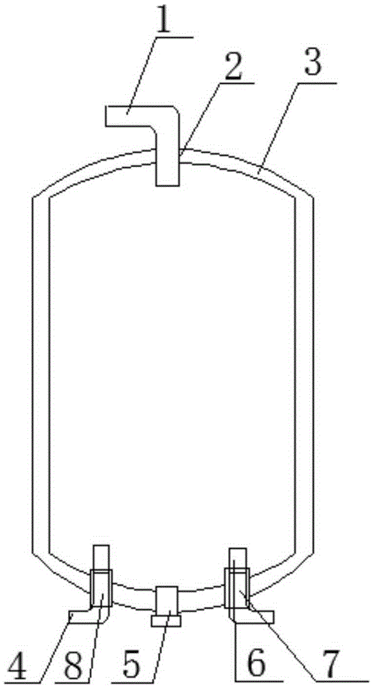
[0024] a. Spinning forming: use the spinning process to process the blank into the reservoir body 3;

[0025] b. Drilling density: Drill a through hole at the joint at the bottom of the reservoir body 3, and weld a plug 5 at the through hole;

[0026] c. Processing of the liquid inlet hole 2 and the liquid outlet hole 7: drill a liquid inlet hole 2 on the upper surface of the liquid reservoir body 3, and drill two liquid outlet holes 7 at positions symmetrical to the center line on the lower surface of the blank;

[0027] d. Welded pipe: weld the liquid inlet pipe 1 at the liquid inlet hole 2, and weld the liquid outlet device at the liquid outlet hole 7.

[0028] The production process of the above-mentioned liquid reservoir, wherein the spinning process includes the following steps:

[0029] (1) Spinning: After the billet is checked for no ...

Embodiment 2

[0032] Embodiment 2: a kind of production technology of liquid reservoir, it is characterized in that: comprise the following steps:

[0033] a. Spinning forming: use the spinning process to process the blank into the reservoir body 3;

[0034] b. Drilling density: Drill a through hole at the joint at the bottom of the reservoir body 3, and weld a plug 5 at the through hole;

[0035] c. Processing of the liquid inlet hole 2 and the liquid outlet hole 7: drill a liquid inlet hole 2 on the upper surface of the liquid reservoir body 3, and drill two liquid outlet holes 7 at positions symmetrical to the center line on the lower surface of the blank;

[0036] d. Welded pipe: weld the liquid inlet pipe 1 at the liquid inlet hole 2, and weld the liquid outlet device at the liquid outlet hole 7.

[0037] The production process of the above-mentioned liquid reservoir, wherein the liquid outlet device includes a straight pipe 6 and an elbow 4 , and the straight pipe 6 and the elbow 4 a...

Embodiment 3

[0039] Embodiment 3: a kind of production technology of liquid reservoir, it is characterized in that: comprise the following steps:

[0040] a. Spinning forming: use the spinning process to process the blank into the reservoir body 3;

[0041] b. Drilling density: Drill a through hole at the joint at the bottom of the reservoir body 3, and weld a plug 5 at the through hole;

[0042] c. Processing of the liquid inlet hole 2 and the liquid outlet hole 7: drill a liquid inlet hole 2 on the upper surface of the liquid reservoir body 3, and drill two liquid outlet holes 7 at positions symmetrical to the center line on the lower surface of the blank;

[0043] d. Welded pipe: weld the liquid inlet pipe 1 at the liquid inlet hole 2, and weld the liquid outlet device at the liquid outlet hole 7.

[0044] The production process of the above-mentioned liquid reservoir, wherein the spinning process includes the following steps:

[0045] (1) Spinning: After the billet is checked for no ...


PUM


Abstract

The invention discloses a production process for a liquid accumulator, and relates to the field of refrigeration equipment. A metal pipe is used as a blank, and the liquid accumulator is obtained through the steps of spin forming, drilled hole sealing, machining of liquid inlets and liquid outlets and pipe welding. According to the production process for the liquid accumulator, the liquid accumulator is integrally formed through the spinning process, and a plug is arranged at the weak position of a spinning connection opening, so that the airtightness of the liquid accumulator is greatly improved, and the service life of the liquid accumulator is greatly prolonged.

Description

technical field [0001] The invention relates to the field of refrigeration equipment, in particular to a production process of a liquid accumulator. Background technique [0002] The liquid receiver is an important part of the compressor, which plays the role of storage, gas-liquid separation, filtration, noise reduction and refrigerant buffering. As follows: The liquid receiver is installed in the air conditioner evaporator and compressor suction pipe, and is a protective part to prevent the liquid refrigerant from flowing into the compressor and causing liquid shock. During the operation of the air conditioning system, it is impossible to guarantee that the refrigerant can be completely vaporized ; That is, the refrigerant coming out of the evaporator will have liquid refrigerant entering the liquid receiver. Since the liquid refrigerant that is not vaporized is heavier than the gas itself, it will directly fall to the bottom of the liquid receiver cylinder, and the vapori...

Claims


Application Information

Patent Timeline
Patent Type & Authority Applications(China)
IPC IPC(8): F25B43/00
Inventor 胡泽华樊锋
Owner WUHU SANHUA REFRIGERATION FITTINGS
Learn More