
A network comprehensive anti-misoperation locking device

It is an anti-error blocking and network integration technology, which is applied in building locks, lock applications, and electric registration locks. Achieve the effect of avoiding lock loss, effective management, and protection of safe operation

Active Publication Date: 2017-11-17
STATE GRID ZHEJIANG ELECTRIC POWER COMPANY TAIZHOU POWER SUPPLY +1
View PDF7 Cites 0 Cited by
  • Summary
  • Abstract
  • Description
  • Claims
  • Application Information

AI Technical Summary

Problems solved by technology

Usually, a simple padlock is used for locking. For equipment with simple functions, this locking method can ensure the safety of the equipment. For important equipment, such as circuit breaker switches on high-voltage switch cabinets, if the lock is opened by mistake , it may be related to the safe operation of large-scale equipment such as main transformers. Therefore, the locking of such equipment is particularly important, and the routinely used anti-misoperation method is to hang a padlock near the operating handle of this type of equipment, and the padlock must be opened when it is necessary to operate. , in the actual operation process, due to problems such as mis-opening of locks and misplacement of locks after unlocking, the reliable operation of the equipment cannot be fully guaranteed, which affects the safe operation of substation equipment and personal safety. It is necessary to invent a new type of anti-misoperation locking The device adds further unlocking restrictions on the basis of the conventional anti-misoperation workflow, which can ensure that a single misoperation will not directly open the lock, realizing the high security of the locked lock

Method used


Image

  • A network comprehensive anti-misoperation locking device
  • A network comprehensive anti-misoperation locking device
  • A network comprehensive anti-misoperation locking device

Examples


Embodiment Construction

[0025] The present invention will be described in detail below with reference to the accompanying drawings and in combination with specific embodiments.

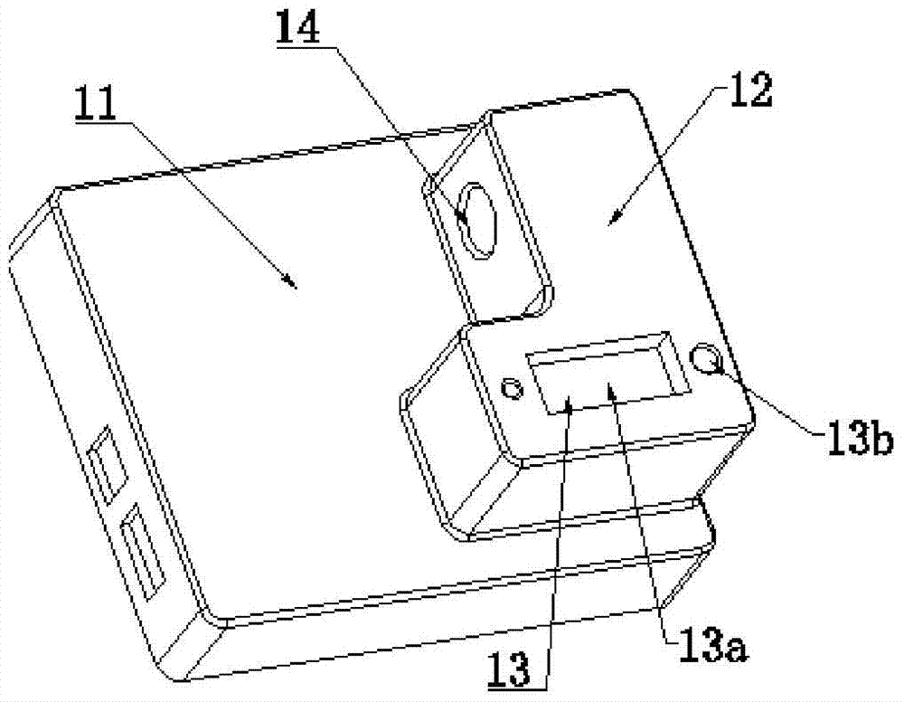
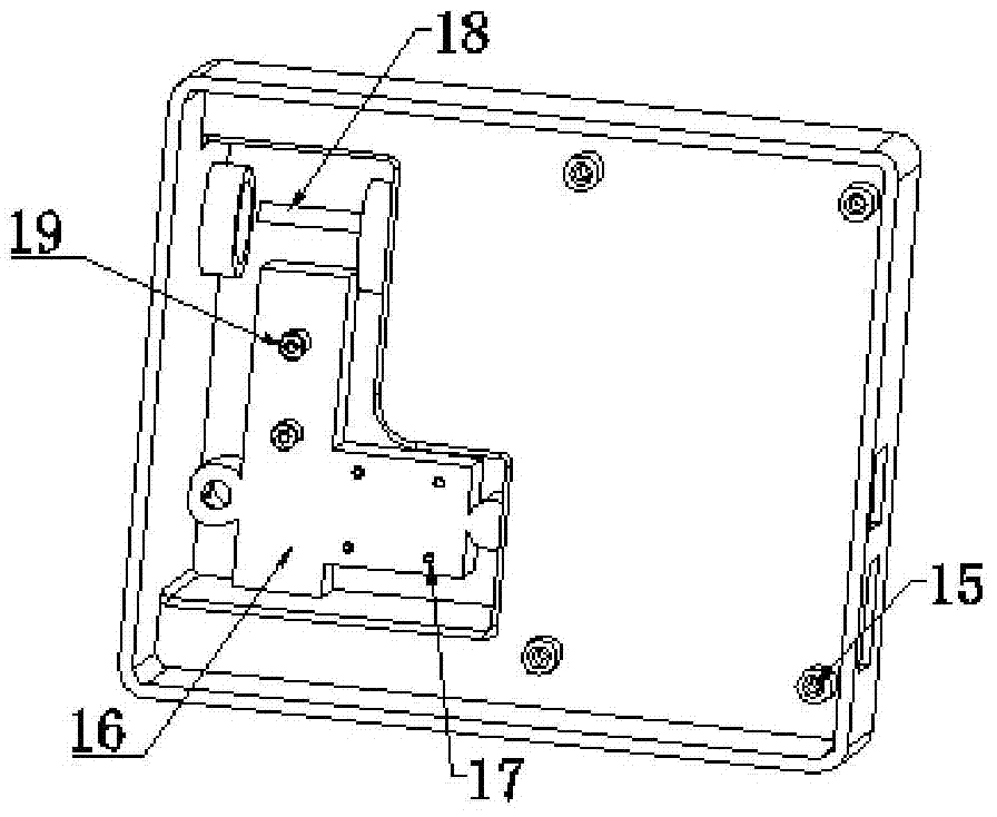
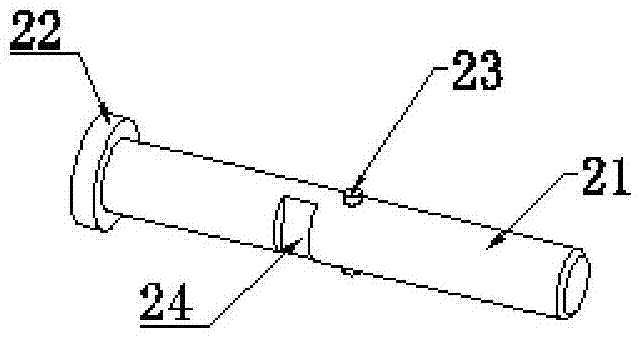
[0026] The invention provides a network comprehensive anti-misoperation locking device, such as figure 1 and Figure 7 As shown, the housing 1 is included, the housing 1 is a square structure, and the housing 1 is composed of a front housing and a rear housing, such as figure 2 As shown, the front shell and the rear shell are fixed as a whole by screws 15 . The front housing front 11 is provided with an L-shaped protrusion 12, and the top surface of the L-shaped protrusion 12 has an anti-unlocking mechanism 13 that cooperates with the anti-misoperation unlocking key. Keyhole 13b; square counterbore 13a is used for installing identification code 3, and keyhole 13b is provided with unlocking bar 4, and anti-error unlocking key is inserted into keyhole 13b and cooperates with unlocking bar 4, and anti-mislocking unlocking ke...


PUM


Abstract

The invention discloses a network comprehensive anti-misoperation locking device, which comprises a housing, a locking bar and a locking pin installed on the housing, the locking bar is provided with a locking groove, and the first end of the locking pin is provided with a locking The second end of the locking pin is connected with a spring, and a local unlocking mechanism and a remote unlocking mechanism are provided at the same time. The remote unlocking mechanism locks the locking pin when it is in the locked state, and the remote unlocking mechanism is connected to the remote At the control end, after the remote control end issues an unlocking command, the remote unlocking mechanism unlocks the locking pin, and the local unlocking mechanism controls the sliding of the locking pin through the anti-mistaken unlocking key, so that the locking head is released from the locking groove, and the locking pin is released. Locking of the locking lever. The present invention realizes the combination of local and remote management of the locking device, avoids accidental unlocking on site or confusion of locks after unlocking and affects the operation safety of equipment, and protects the safe operation of important equipment in the power system.

Description

technical field [0001] The invention relates to a locking device for substations, power plants and other equipment, in particular to a device with reliable locking applied in substations, power plants and other occasions. Background technique [0002] There are a lot of equipment in the power industry. If the operation is careless or mishandled, the equipment will be damaged in the slightest, and the personal safety will be caused in the serious one. Therefore, such equipment is usually locked with locks with anti-misoperation locking function. Usually, a simple padlock is used for locking. For equipment with simple functions, this locking method can ensure the safety of the equipment. For important equipment, such as circuit breaker switches on high-voltage switch cabinets, if the lock is opened by mistake , it may be related to the safe operation of large-scale equipment such as main transformers. Therefore, the locking of such equipment is particularly important, and the ...

Claims


Application Information

Patent Timeline
Patent Type & Authority Patents(China)
IPC IPC(8): E05B49/00E05B65/00
Inventor 沈君张劲沈一平钱平王昕汤义勤方家麟潘激扬张东波陈坚陈泷王琪周戈
Owner STATE GRID ZHEJIANG ELECTRIC POWER COMPANY TAIZHOU POWER SUPPLY
Learn More