A lifting type tool setting device installation mechanism
A technology of installation mechanism and tool setting instrument, which is applied in the direction of feeding device, automatic control device, metal processing machinery parts, etc., can solve the problems of affecting the processing range of the workpiece, prone to vibration, insufficient rigidity, etc., and achieves the improvement of machine tool processing accuracy and processing range, ensure the accuracy of installation and use, and avoid the effect of knife collision
- Summary
- Abstract
- Description
- Claims
- Application Information
AI Technical Summary
Problems solved by technology
Method used
Image
Examples
Embodiment 1
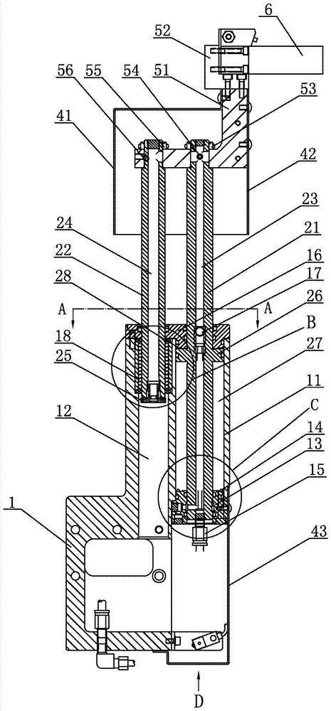
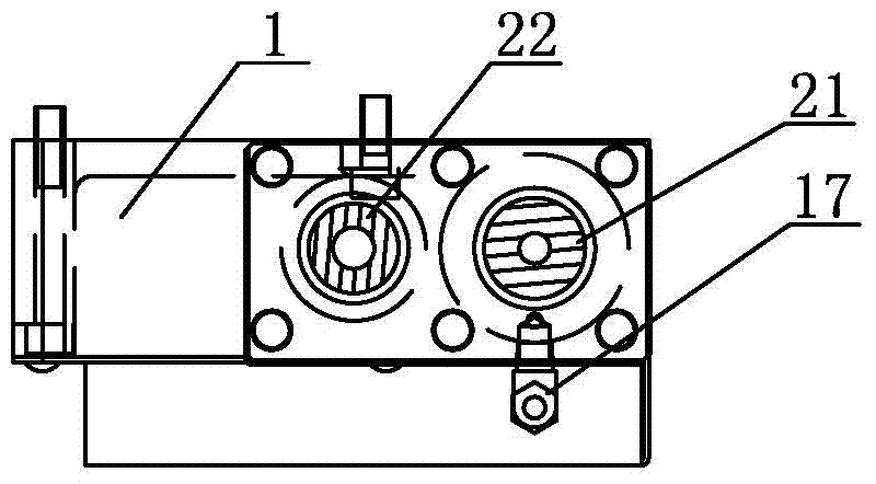
[0024] The installation mechanism of the lifting tool setting instrument in Embodiment 1, as shown in the figure, includes a box body 1 and a drive unit, a detection unit, and a protection unit arranged on the box body 1. After installation, the box body 1 is fixed on the workbench 7 by screws. The side of the drive unit is connected with a support 51, the top of the support 51 is fixed with a mount 52, the mount 52 is used to install the tool setting instrument 6, and the drive unit is used to drive the tool setting instrument 6 to rise or fall.
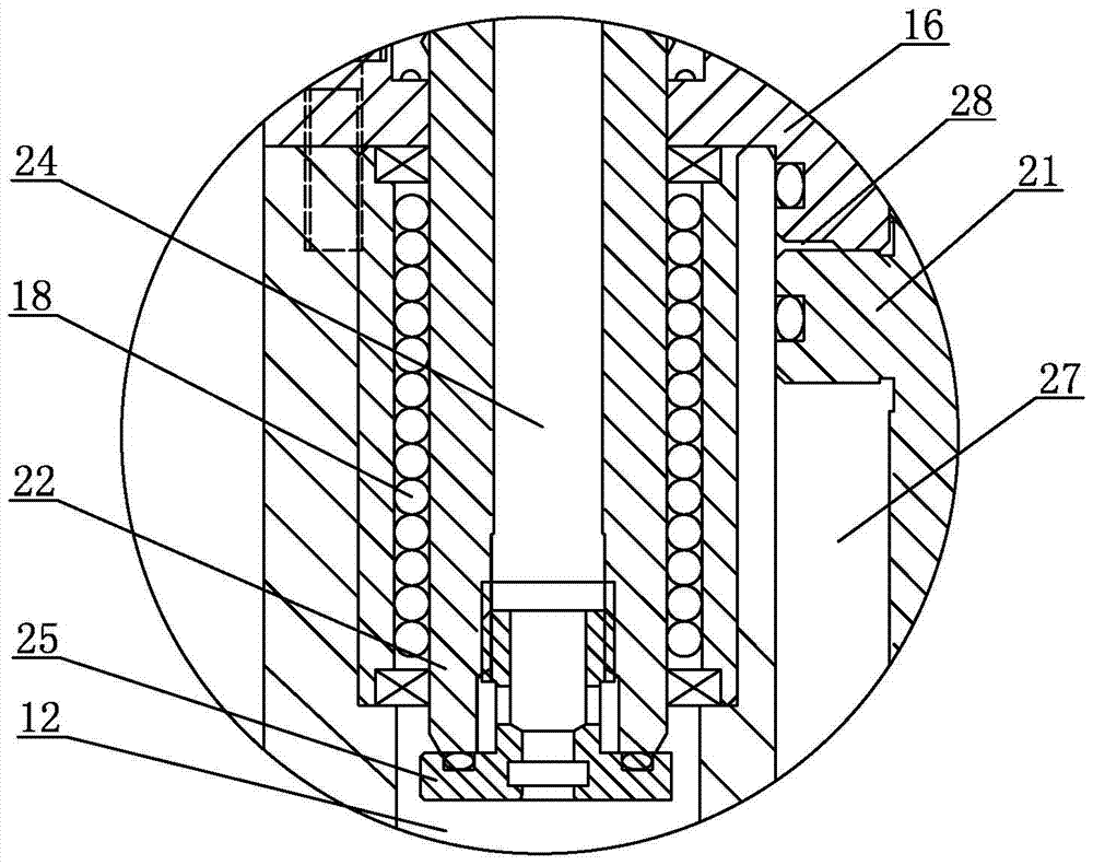
[0025]In Embodiment 1, the drive unit includes a first air source, a second air source, a piston rod 21 and a guide rod 22. The middle part of the piston rod 21 is provided with a first axial through hole 23, and the middle part of the guide rod 22 is provided with a second The axial through hole 24, the bottom end of the guide rod 22 is equipped with a pipeline joint 25, the first chamber 11 and the second chamber 12 separated from ...
Embodiment 2
[0027] The installation mechanism of the lifting type tool setting instrument in embodiment 2 is basically the same as the structure of the installation mechanism in embodiment 1, the difference is that in embodiment 2, such as Figure 7 As shown in the pneumatic assembly drawing, the first air source and the second air source are supplied by the air source supply unit. The air source supply unit includes a T-shaped joint 81, a solenoid valve 82, two mufflers 83, a straight-through joint 84, and a speed control unit. Valve 85, quick-change joint 86 and pressure switch 87, straight-through joint 84 is installed on the inlet port of solenoid valve 82, two mufflers 83 are respectively arranged on both sides of straight-through joint 84, quick-change joint 86 is installed on the pressure switch 87, T The inlet end of the T-shaped joint 81 is connected with the total gas source, and the outlet end of the T-shaped joint 81 includes a first branch 811 and a second branch 812, the firs...
PUM
 Abstract
Description
Claims
Application Information
 - Generate Ideas
- Intellectual Property
- Life Sciences
- Materials
- Tech Scout
- Unparalleled Data Quality
- Higher Quality Content
- 60% Fewer Hallucinations
Browse by: Latest US Patents, China's latest patents, Technical Efficacy Thesaurus, Application Domain, Technology Topic, Popular Technical Reports.
© 2025 PatSnap. All rights reserved.Legal|Privacy policy|Modern Slavery Act Transparency Statement|Sitemap|About US| Contact US: help@patsnap.com


