
Centrifugal pendulum

A technology of centrifugal force pendulum and pendulum quality, applied in the field of centrifugal force pendulum, which can solve problems such as elastic body fracture, hydraulic or mechanical damage, and achieve the effect of improving manufacturability and reducing damage rate

Active Publication Date: 2017-05-10
SCHAEFFLER TECH AG & CO KG
View PDF6 Cites 0 Cited by
  • Summary
  • Abstract
  • Description
  • Claims
  • Application Information

AI Technical Summary

Problems solved by technology

As a result, part of the elastomer may break, so that the elastomer can no longer fully perform its function
Furthermore, broken elastomeric pieces can move uncontrollably in the region of the centrifugal pendulum and cause subsequent hydraulic or mechanical damage

Method used


Image

  • Centrifugal pendulum
  • Centrifugal pendulum
  • Centrifugal pendulum

Examples


Embodiment Construction

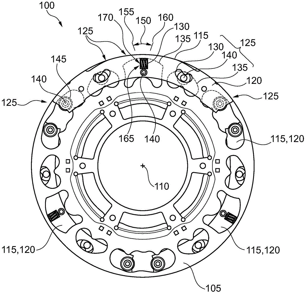
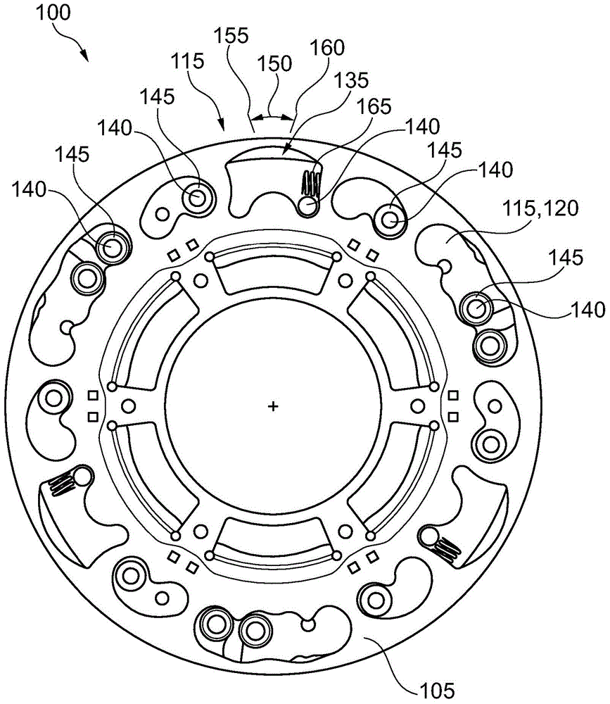
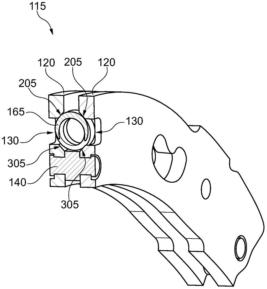
[0022] figure 1 A first view is shown of a centrifugal force pendulum 100 for damping rotational or torsional vibrations, in particular in a drive train of a motor vehicle. The centrifugal pendulum 100 includes a pendulum flange 105 with an axis of rotation 110 and one or more pendulum masses 115 . In the illustrated embodiment, each pendulum mass 115 is formed by a first and a second mass element 120 , which are located on different axial sides of the pendulum flange 105 . In this illustration, pendulum masses 115 are each in a neutral position. Of the three pendulum masses 115 shown by way of example, only the mass element 120 remote from the observer is shown in each of the lower two pendulum masses. In the third pendulum mass 115 shown above, the mass element 120 facing the viewer is shown transparently.

[0023] Each pendulum mass 115 is mounted on the pendulum flange 105 displaceably in the plane of rotation of the pendulum flange 105 by means of one or more link guid...


PUM


Abstract

A centrifugal force pendulum comprises a pendulum flange, a pendulum mass and a rail guide for guiding the pendulum mass on the pendulum flange on a predefined pendulum path. For braking the pendulum mass relative to the pendulum flange, a spring element is provided in the region of one end of the pendulum path.

Description

technical field [0001] The invention relates to a centrifugal force pendulum. In particular, the invention relates to a centrifugal pendulum having a pendulum mass and a spring element for delimiting a pivot path of the pendulum mass. Background technique [0002] A centrifugal pendulum is a vibration damper used to damp rotational and torsional vibrations. Centrifugal pendulums comprise a pendulum flange and one or more pendulum masses, which are mounted displaceably in a plane of rotation on the pendulum flange. If the rotation of the pendulum flange about its axis of rotation is subject to inhomogeneities, this rotation causes a displacement of the pendulum mass on the pendulum flange, whereby it buffers energy and thereby reduces the inhomogeneity. [0003] A link guide is usually provided in order to guide the pendulum mass along the pivoting path and delimit the pivoting path. If the pendulum mass reaches the end of the pivot path, the pin of the link guide generall...

Claims


Application Information

Patent Timeline
Patent Type & Authority Patents(China)
IPC IPC(8): F16F15/14
CPCF16F15/145
Inventor C·丁格J·霍夫曼
Owner SCHAEFFLER TECH AG & CO KG
Learn More