
Asynchronous motor rotor time constant online recognition method based on improved reactive power model

A rotor time constant, asynchronous motor technology, applied in the direction of control generator, motor generator control, electronic commutation motor control, etc., to achieve the effect of easy parameter setting

Inactive Publication Date: 2016-01-06
HEFEI UNIV OF TECH
View PDF4 Cites 8 Cited by
  • Summary
  • Abstract
  • Description
  • Claims
  • Application Information

AI Technical Summary

Problems solved by technology

[0008] The purpose of the present invention is to provide an online identification method for the rotor time constant of asynchronous motors based on the improved reactive power model in view of the problems existing in the existing rotor time constant identification method based on the reactive power model

Method used


Image

  • Asynchronous motor rotor time constant online recognition method based on improved reactive power model
  • Asynchronous motor rotor time constant online recognition method based on improved reactive power model
  • Asynchronous motor rotor time constant online recognition method based on improved reactive power model

Examples


Embodiment Construction

[0045] Below in conjunction with accompanying drawing, the technical scheme of the present invention is described in further detail:

[0046] see figure 1 , the implementation process of the present invention is as follows:

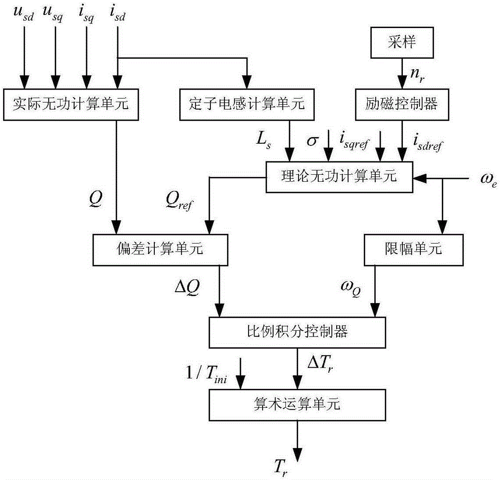
[0047] Step 1: Collect the d-axis component i of the motor stator current sd , q-axis component isq and the motor stator voltage d-axis component u sd , q-axis component u sq , the actual reactive power Q of the motor is obtained through the actual reactive power calculation unit, where:

[0048] Motor stator current d-axis component i sd , q-axis component i sq It is the motor feedback current required by the motor indirect vector control system to establish current closed-loop control, which is obtained by sampling the three-phase current of the motor stator through synchronous coordinate transformation;

[0049] Motor stator voltage d-axis component u sd , q-axis component u sq is the output value of the motor indirect vector control current lo...


PUM


Abstract

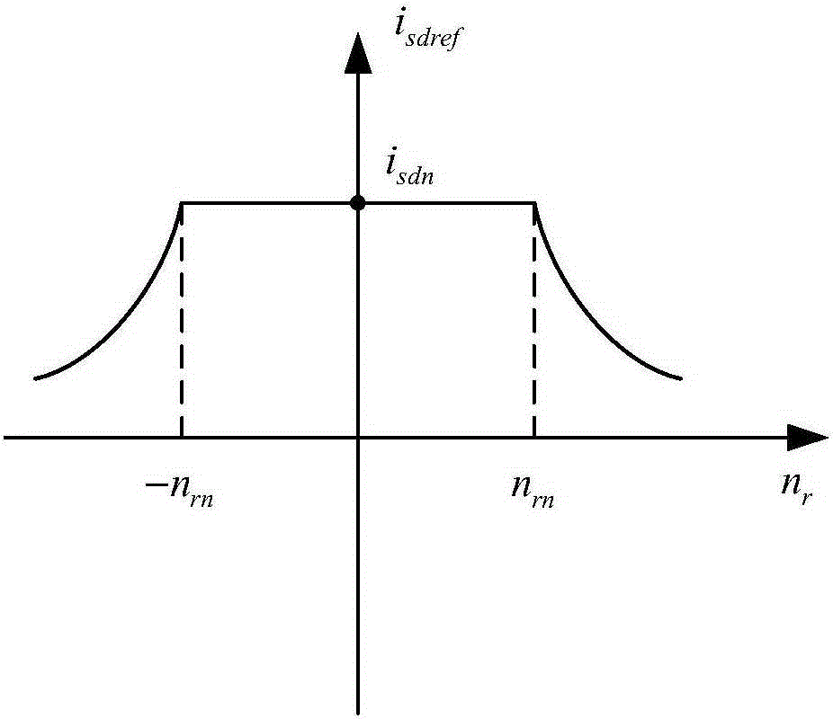
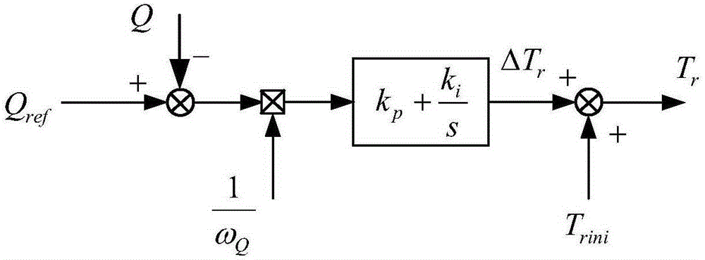
The invention discloses an asynchronous motor rotor time constant online recognition method based on an improved reactive power model. According to the invention, a feed-forward for a motor stator frequency, subjected to the amplitude limiting treatment, is introduced in a conventional reactive power model. The method comprises the steps of sampling and obtaining the actual reactive power Q of a motor by an actual reactive power calculation unit; obtaining the stator inductance Ls of the motor by a stator inductance calculation unit; obtaining the reference value Isdref of the d-axis component of the stator current of the motor by an excitation controller; obtaining the theoretical reactive power Qref of the motor by a theoretical reactive power calculation unit; obtaining the reactive power deviation delta Q by a deviation calculation unit; obtaining a feed-forward value omega Q by an amplitude limiting unit; obtaining a correction value delta Tr for the rotor time constant Tr of the motor by a proportional-integral controller; and calculating the rotor time constant Tr of the motor by an arithmetic operation unit. The above method can be applied in the four-quadrant operation scenarios for the motor. By means of the method, the proportional-integral controller of the reactive power model is easy to set. At the same time, the similar rotor time constant convergence dynamic process can be obtained during the high-speed and low-speed operation process of the motor.

Description

technical field [0001] The invention relates to the field of motor control, in particular to an on-line identification method for the rotor time constant of an asynchronous motor based on an improved reactive power model. Background technique [0002] Indirect vector control of asynchronous motors is widely used in industry because of its simplicity, reliability and fast response. In indirect magnetic field orientation, the rotor time constant is a key parameter. If the rotor time constant used for orientation control is inconsistent with the actual value of the motor, it will lead to inaccurate magnetic field orientation of the motor, coupling of the motor stator current flux component and torque component, etc. . During the operation of the motor, the change of excitation and temperature will cause the rotor time constant to change continuously. The rotor inductance in the rotor time constant that changes with the change of the motor excitation can be adjusted online afte...

Claims


Application Information

Patent Timeline
Patent Type & Authority Applications(China)
IPC IPC(8): H02P21/14
Inventor 张兴曹朋朋杨淑英谢震郭磊磊李浩源
Owner HEFEI UNIV OF TECH
Learn More