Self-excited type BJT type bridgeless Sepic PFC rectifying circuit
A rectifier circuit, self-excited technology, applied to electrical components, AC power input conversion to DC power output, output power conversion devices, etc., can solve problems such as low drive efficiency, complex MOSFET drive circuit, and poor self-starting performance , to achieve the effect of high driving efficiency, easy self-starting and simple circuit
- Summary
- Abstract
- Description
- Claims
- Application Information
AI Technical Summary
Problems solved by technology
Method used
Image
Examples
Embodiment 1
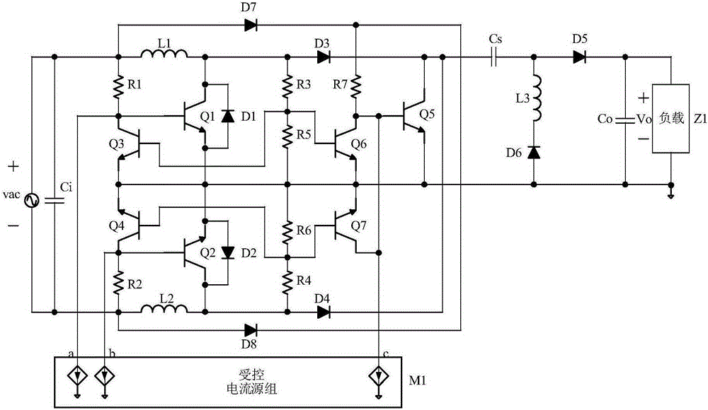
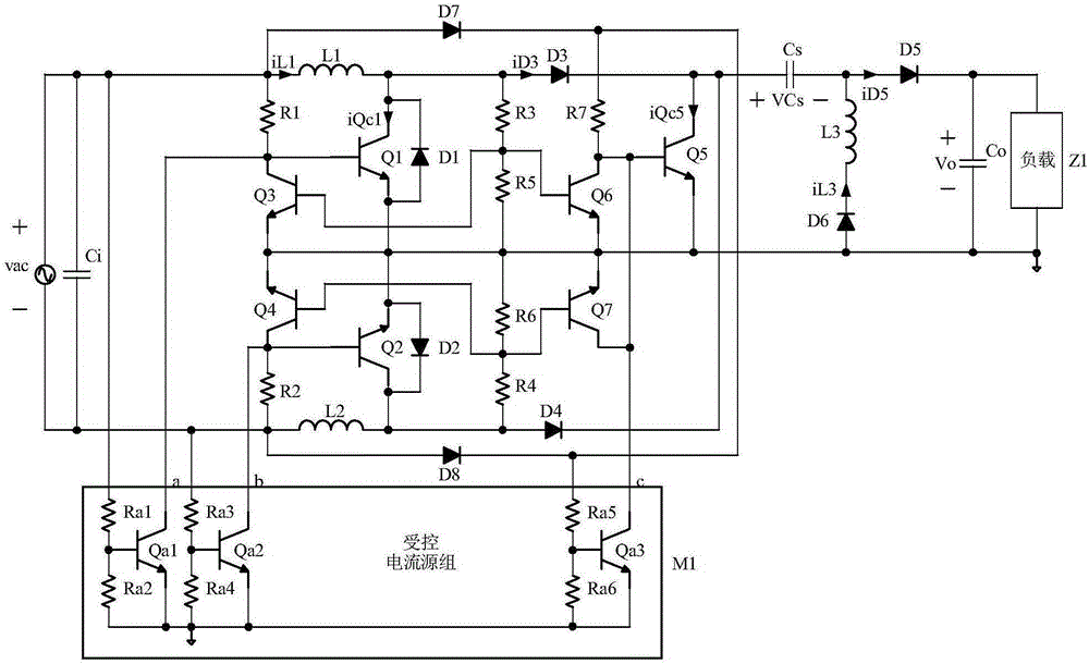
[0025] Embodiment 1: refer to figure 1 , image 3 , Figure 5 and Figure 6 , Embodiment 1 of the present invention has an input voltage feedforward function, which consists of input capacitor Ci, NPN type BJT tube Q1, NPN type BJT tube Q2, NPN type BJT tube Q3, NPN type BJT tube Q4, NPN type BJT tube Q5, NPN Type BJT tube Q6, NPN type BJT tube Q7, diode D1, diode D2, diode D3, diode D4, diode D5, diode D6, diode D7, diode D8, inductor L1, inductor L2, inductor L3, capacitor Cs, output capacitor Co , resistor R1, resistor R2, resistor R3, resistor R4, resistor R5, resistor R6, resistor R7, controlled current source group M1. Among them, the controlled current source M1 is composed of NPN BJT transistor Qa1, NPN BJT transistor Qa2, NPN BJT transistor Qa3, resistor Ra1, resistor Ra2, resistor Ra3, resistor Ra4, resistor Ra5, resistor Ra6.
[0026] Such as image 3 As shown, one end of the input capacitor Ci is simultaneously connected to the positive end of the AC power sup...
Embodiment 2
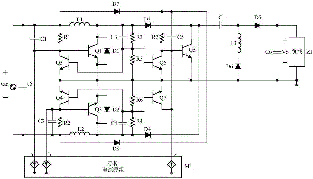
[0038] Embodiment 2: refer to figure 1 , Figure 4 , Figure 7 and Figure 8 , Embodiment 2 of the present invention has output voltage stabilizing function, and it is composed of input capacitor Ci, NPN type BJT tube Q1, NPN type BJT tube Q2, NPN type BJT tube Q3, NPN type BJT tube Q4, NPN type BJT tube Q5, NPN type BJT tube Q6, NPN type BJT tube Q7, diode D1, diode D2, diode D3, diode D4, diode D5, diode D6, diode D7, diode D8, inductor L1, inductor L2, inductor L3, capacitor Cs, output capacitor Co, Composed of resistor R1, resistor R2, resistor R3, resistor R4, resistor R5, resistor R6, resistor R7, and controlled current source group M1. Among them, the controlled current source group M1 is composed of an NPN BJT transistor Qb1, an NPN BJT transistor Qb2, an NPN BJT transistor Qb3, and a voltage regulator transistor VZ1.
[0039] Such as Figure 4 As shown, one end of the input capacitor Ci is simultaneously connected to the positive end of the AC power supply vac, o...
PUM
 Abstract
Description
Claims
Application Information
 - R&D
- Intellectual Property
- Life Sciences
- Materials
- Tech Scout
- Unparalleled Data Quality
- Higher Quality Content
- 60% Fewer Hallucinations
Browse by: Latest US Patents, China's latest patents, Technical Efficacy Thesaurus, Application Domain, Technology Topic, Popular Technical Reports.
© 2025 PatSnap. All rights reserved.Legal|Privacy policy|Modern Slavery Act Transparency Statement|Sitemap|About US| Contact US: help@patsnap.com


