Eureka AIR delivers breakthrough ideas for toughest innovation challenges, trusted by R&D personnel around the world.

Energy control method for urban rail supercapacitor energy storage system

A technology of super capacitors and energy storage systems, applied in current collectors, electric vehicles, electrical components, etc., can solve the problems of small variation range of charging threshold and discharge threshold, and achieve stable and safe operation, reduce line loss, and improve use. effect of life

Active Publication Date: 2017-12-01
BEIJING JIAOTONG UNIV
View PDF6 Cites 0 Cited by
  • Summary
  • Abstract
  • Description
  • Claims
  • Application Information

AI Technical Summary

Problems solved by technology

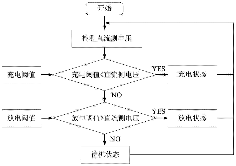
[0013] like figure 2 As shown, in the existing energy control method of urban rail supercapacitor energy storage system, the charging threshold and discharging threshold are basically set to be constant or have a small variation range

Method used


Image

  • Energy control method for urban rail supercapacitor energy storage system
  • Energy control method for urban rail supercapacitor energy storage system
  • Energy control method for urban rail supercapacitor energy storage system

Examples


Embodiment Construction

[0062] The present invention will be described in further detail below in conjunction with the accompanying drawings.

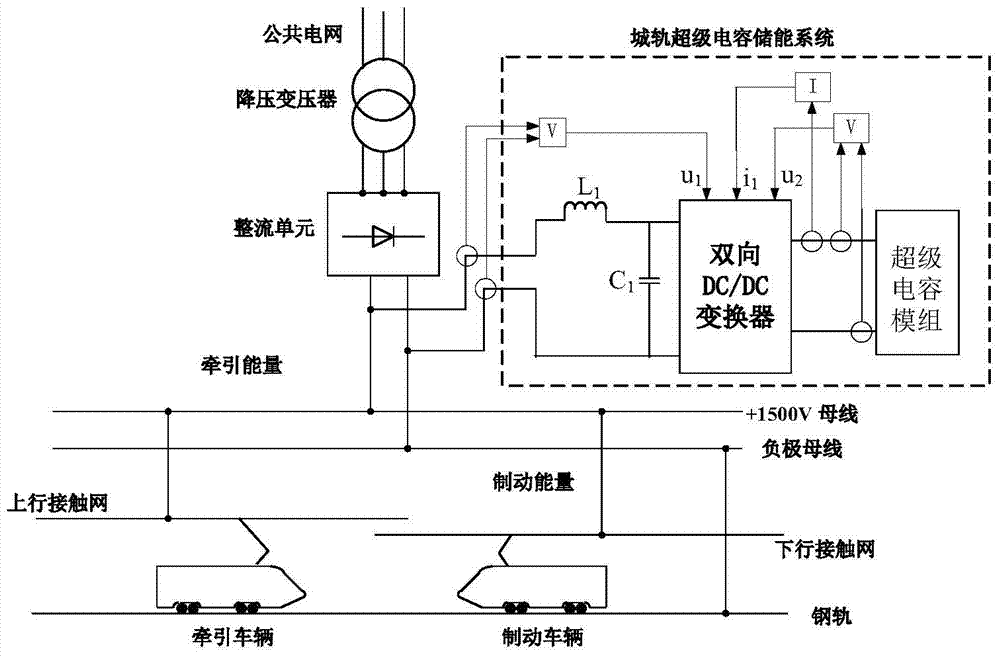
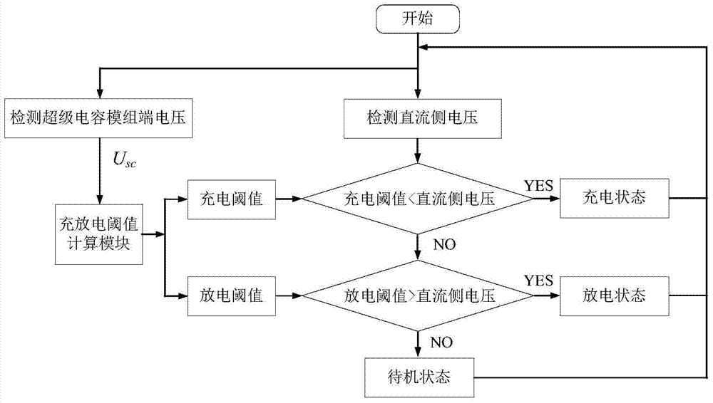
[0063] like figure 1 , 3 As shown, the energy control method of the urban rail supercapacitor energy storage system of the present invention comprises the following steps:

[0064] In each control cycle, the voltage U of the DC power supply network is collected separately dc and supercapacitor module terminal voltage U sc , to collect the output branch current I of the supercapacitor module sc ,

[0065] In each control cycle, based on the super capacitor module terminal voltage U sc , the charging threshold U is output in real time by the charging and discharging threshold calculation module char and discharge threshold U dis ;

[0066] According to the charging threshold, discharging threshold and DC power supply network voltage (also known as DC side voltage) U dc The size relationship between them determines that the current control cycle of the ...


PUM


Abstract

The invention relates to an energy control method for an urban rail supercapacitor energy storage system, comprising the following steps: in each control cycle, respectively collecting the DC power supply network voltage Udc and the supercapacitor module terminal voltage Usc, and collecting the output of the supercapacitor module Branch current Isc, in each control cycle, based on the terminal voltage Usc of the supercapacitor module, the charging threshold Uchar and discharging threshold Udis are output in real time by the charging and discharging threshold calculation module; The size relationship between them determines that the current control cycle of the urban rail supercapacitor energy storage system should be in the charging state, discharging state or standby state. The energy control method of the present invention enables multiple sets of urban rail supercapacitor energy storage systems to work in coordination, enables the urban rail supercapacitor energy storage system to fully and effectively absorb the braking energy of the train, and improves the energy utilization efficiency of the urban rail power supply system. And suppress the fluctuation of the DC side voltage of the power supply system.

Description

technical field [0001] The invention relates to the technical field of urban rail transit energy storage and energy saving, in particular to an energy control method for an urban rail supercapacitor energy storage system. Background technique [0002] Urban rail transit has the following characteristics: the distance between stations is short, urban rail trains (referred to as trains for short) start and brake frequently, and regenerative braking is a braking method that can regenerate the kinetic energy of trains into electrical energy and generate controllable power . It effectively reduces the burden and wear of the mechanical brake device, thus becoming the main way of train braking. Regenerative braking can feed back 20% to 60% of electric energy, and has become the main means of saving train energy consumption. The train uses regenerative braking to feed regenerative braking energy back to the catenary. [0003] Since a typical traction substation adopts a diode rect...

Claims


Application Information

Patent Timeline
Patent Type & Authority Patents(China)
IPC IPC(8): H02J7/34
Inventor 杨中平林飞陈怀鑫夏欢王俊兴李旭阳王彬孙湖
Owner BEIJING JIAOTONG UNIV
Why Eureka
Eureka Blog
Learn More