Load shedding design method for intershaft bearing of aeroengine

An aero-engine and intermediary technology, applied in the direction of engine components, machines/engines, mechanical equipment, etc., can solve problems such as synchronous impact, and achieve the effects of improving efficiency, clear physical meaning, and easy drawing

Inactive Publication Date: 2016-01-06
NORTHWESTERN POLYTECHNICAL UNIV
View PDF4 Cites 6 Cited by
  • Summary
  • Abstract
  • Description
  • Claims
  • Application Information

AI Technical Summary

Problems solved by technology

[0028] In order to overcome the problem of synchronous impact of the intermediary bearing of the aero-engine in the prior art during operation and reduce the failure rate of the intermediary bearing, the present invention proposes a load reduction design method for the intermediary bearing of the aero-engine

Method used


Image

  • Load shedding design method for intershaft bearing of aeroengine
  • Load shedding design method for intershaft bearing of aeroengine
  • Load shedding design method for intershaft bearing of aeroengine

Examples


Embodiment Construction

[0073] This embodiment is a method for the load reduction design of an aero-engine intermediary bearing, and the specific process is:

[0074] Step 1, determining the rotational speed ratio of the high-pressure rotor and the low-pressure rotor in the dual-rotor engine.

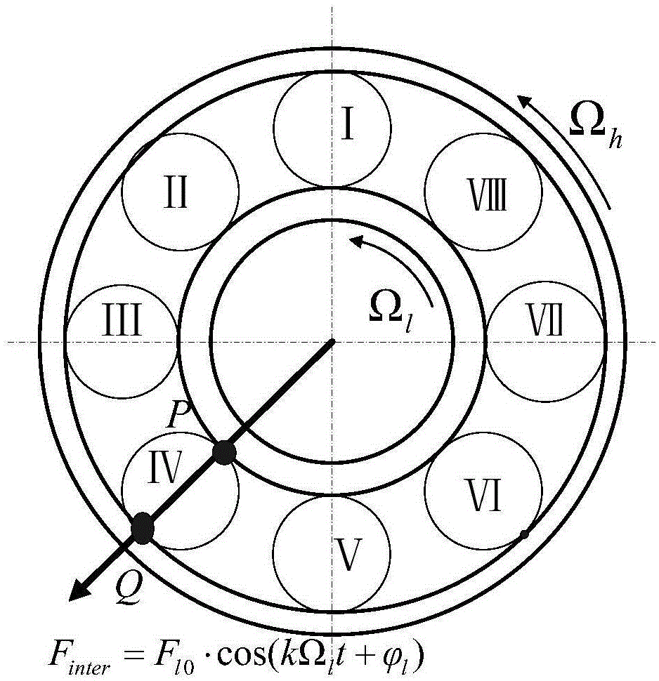
[0075]According to the principle of equal speed intervals, N speed operating points are selected within the working speed range of the aero-engine from idle speed to maximum speed. According to the high-pressure rotor design speed and low-pressure rotor design speed of the engine, calculate the high / low pressure rotor speed ratio under each speed conditionγ i =Ω H,i / Ω L,i =n 2,i / n 1,i ,i=(1,2...N). Among them, Ω H is the rotational angular velocity of the high voltage rotor, Ω L is the rotational angular velocity of the low pressure rotor. no 2 is the design speed of the high-pressure rotor, and its dimension is rev / min; n 1 is the design speed of the low-pressure rotor, and its dimension is rev / m...


PUM


Abstract

The invention discloses a load shedding design method for an intershaft bearing of an aeroengine, and provides a principle of avoiding a synchronous impact on the intershaft bearing. According to the method, selecting N revolving speed points in an operating range of the aeroengine from a slow speed of a vehicle to a maximal speed, and determining inner ring characteristic frequencies multiplication and outer ring characteristic frequencies multiplication of the intershaft bearing under each revolving speed; marking blade number of a fan; determining whether distances of the blade number of the fans and an integer multiple thereof to the inner ring characteristic frequencies multiplication and to the outer ring characteristic frequencies multiplication are smaller than 2%; and If the revolving speed section that meets the condition is greater than 10% of an engine working revolving speed range, then adjusting the blade number or a rotation speed ratio of a high/low pressure rotor to 90% of the engine working revolving speed range, wherein the distance of the blade number of the fans and an integer multiple thereof to the inner ring characteristic frequencies multiplication and to the outer ring characteristic frequencies multiplication of the intershaft bearing are greater than 2%. The method of the present invention effectively avoids the occurrence of a synchronous impact on the intershaft bearing.

Description

technical field [0001] The invention relates to the field of aero-engine structural dynamics design, in particular to a load reduction method for an aero-engine intermediate bearing. Background technique [0002] The intermediate bearing is the key load-bearing and transmission part in the twin-rotor aero-engine. Its outer ring is mounted on the high-pressure turbine rotor and its inner ring is mounted on the low-pressure turbine rotor; or conversely, the outer ring is mounted on the low-pressure turbine rotor and the inner ring is mounted on the high-pressure turbine rotor. Therefore, the inner and outer rings of the intermediate bearing rotate simultaneously. The intermediate bearing works in the environment of high temperature, alternating load, and difficult lubrication, and is prone to failure. Once a failure occurs, it will seriously threaten the safe operation of the engine. Reducing the dynamic load of the intermediate bearing is an effective way to reduce the failu...

Claims


Application Information

Patent Timeline
Patent Type & Authority Applications(China)
IPC IPC(8): G06F17/50F01D25/16
Inventor 王俨剀廖明夫王四季杨伸记
Owner NORTHWESTERN POLYTECHNICAL UNIV
Why Eureka
Try Eureka