Vacuum frame and sealing method for euv lithography equipment

A technology of lithography equipment and frame, which is applied in the direction of microlithography exposure equipment, photolithography exposure device, etc., can solve the problems of complex structure and low reliability of implementation, and achieve flexible manual operation, small space, and reusable gas tightness effect

Active Publication Date: 2017-08-29
SHANGHAI MICRO ELECTRONICS EQUIP (GRP) CO LTD
View PDF2 Cites 0 Cited by
  • Summary
  • Abstract
  • Description
  • Claims
  • Application Information

AI Technical Summary

Problems solved by technology

However, the structure of the scheme is too complicated and the reliability of implementation is low.

Method used


Image

  • Vacuum frame and sealing method for euv lithography equipment
  • Vacuum frame and sealing method for euv lithography equipment
  • Vacuum frame and sealing method for euv lithography equipment

Examples


Embodiment Construction

[0027] Specific embodiments of the present invention will be described in detail below in conjunction with the accompanying drawings.

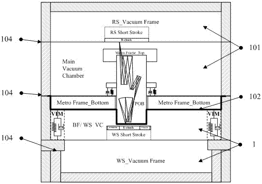
[0028] figure 1 A vacuum frame of a lithographic apparatus according to Embodiment 1 of the present invention is schematically shown. The mask part (vacuum degree requirement is 10-7~10-9mbar) and the silicon wafer exposure part (vacuum degree requirement is 10-5~10-7mbar) require different vacuum degrees, so the main substrate is used as the interface to The vacuum chamber is divided into a main vacuum chamber (Main Vacuum Chamber) 101 and a workpiece table vacuum chamber (WS Vacuum Chamber) 1, and the dynamic balance of high vacuum is realized by means of pumping and exhausting respectively. Several sealing surfaces 104 are also included between each vacuum chamber. The main substrate serves as the interface 102 between the main vacuum chamber 101 and the vacuum chamber 1 of the workpiece table.

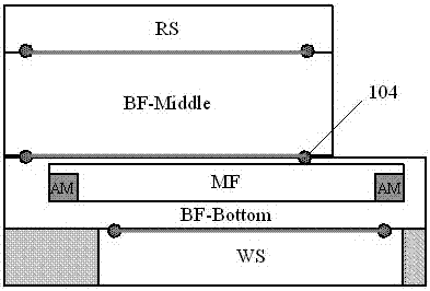
[0029] The layout diagram of the vacuum ...


PUM


Abstract

The invention discloses a vacuum frame for a EUV (extreme ultraviolet) lithography device. The vacuum frame is characterized by comprising a main substrate; the internal space of the vacuum frame is divided into a main vacuum cavity and a workpiece table vacuum cavity by the main substrate; the main vacuum cavity comprises an objective lens and a mask table of the EUV lithography device; and the work table vacuum cavity comprises a workpiece table and a measurement system of the EUV lithography device.

Description

technical field [0001] The invention relates to the field of integrated circuit equipment manufacturing, in particular to a vacuum sealing device and a sealing method for EUV lithography equipment. Background technique [0002] EUVL (Extreme ultraviolet lithography) is the most promising next-generation lithography technology. Compared with traditional lithography machines, on the one hand, EUVL has a shorter wavelength of 5-20nm, which can achieve higher resolution. On the other hand, there are also new problems. One of the most notable features of EUVL is the use of extreme ultraviolet light with a wavelength of 13.5nm. Any substance has a strong absorption effect on this wavelength of radiation. Therefore, the entire lithography machine system needs to work in a high vacuum environment, and the high vacuum involved Acquisition, contamination control, and chamber isolation have become key technologies for the development of EUVL. [0003] In the present invention, an EU...

Claims


Application Information

Patent Timeline
Patent Type & Authority Patents(China)
IPC IPC(8): G03F7/20
Inventor 戴乐薇高原吴飞
Owner SHANGHAI MICRO ELECTRONICS EQUIP (GRP) CO LTD
Why Eureka
Try Eureka