
Parallel type bionic knee-hip joint testing machine

A technology of hip joint and knee joint, which is applied in the field of parallel bionic knee-hip joint testing machine, achieves the effects of high precision, easier speed control, stable and compact structure

Inactive Publication Date: 2016-01-06
CHINA UNIV OF MINING & TECH
View PDF9 Cites 7 Cited by
  • Summary
  • Abstract
  • Description
  • Claims
  • Application Information

AI Technical Summary

Problems solved by technology

Ball testing machines such as the disc and surface contact testing machines used by Wang et al. use vertical axial rotation instead of reciprocating motion; prosthetic force and motion direct control testing machines are mainly foreign, and Walker and Hsish et al. found that , the transitional assembly of the tibial ankle fossa and the femoral ankle fossa is the most reasonable configuration form; the testing machine developed by Pual et al. uses pneumatic four-bar linkages to realize the anteroposterior displacement of the femoral prosthesis, and the research direction turns to the direction of fine movement, but it still can only imitate some Sports; simulating knee joint muscle force group testing machine is a kind of muscle group that uses motors, cylinders or hydraulic cylinders to simulate the muscle groups related to the human lower limbs and knee joints, trying to more accurately simulate the real stress and movement of the knee joint. state

Method used


Image

  • Parallel type bionic knee-hip joint testing machine
  • Parallel type bionic knee-hip joint testing machine
  • Parallel type bionic knee-hip joint testing machine

Examples


Embodiment Construction

[0020] The present invention will be further described below in conjunction with the accompanying drawings.

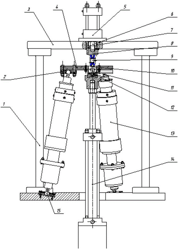
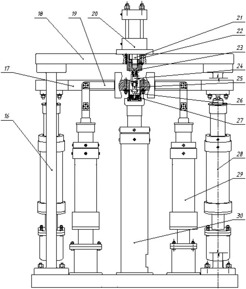
[0021] Such as Figure 6 , 7 A parallel bionic knee-hip testing machine is shown, including a hip joint testing device and a knee joint testing device, the hip joint testing device is located above the knee joint testing device, and a second moving platform is shared between the two 17.

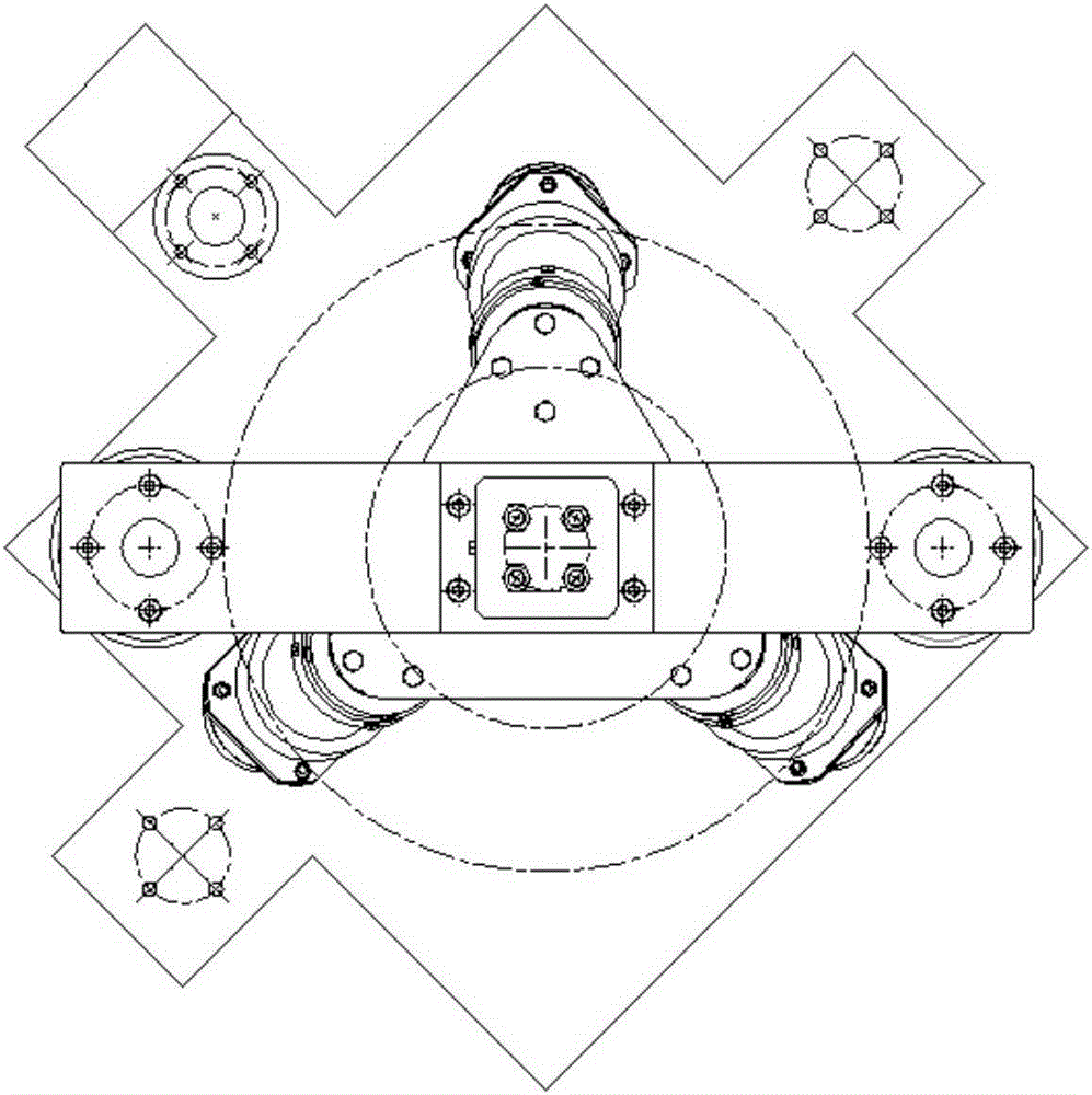
[0022] Such as figure 1 , 2 , 3 and 4, the hip joint test device includes a first support column 1, a first upper support plate 3, a second moving platform 17, a first middle pillar 14, a first moving platform 4, hip joint test components, Hip joint hydraulic loading system and three identical hip joint active branch chains 13, one end of the first support column 1 is vertically fixed on the second moving platform 19, and the other end of the first support column 1 is supported by a first The upper support plate 3, the first upper support plate 3 is parallel to the second moving ...


PUM


Abstract

The invention discloses a parallel type bionic knee-hip joint testing machine comprising a hip joint test apparatus and a knee joint test apparatus. The hip joint test apparatus is arranged on the knee joint test apparatus and the two apparatuses share a same moving platform. According to the invention, on the basis of cooperation of mechanisms, moving situations and moving environments of the knee joint and hip joint of the human body can be simulated actually. Moreover, the structure is compact, the installation becomes convenient, and the testing effect is good.

Description

technical field [0001] The invention discloses a parallel bionic knee-hip joint testing machine, and relates to a parallel bionic knee-hip joint testing machine in a hydraulic system loading and parallel driving mode. The friction and wear test of the artificial knee joint material adopts a parallel driving method, which belongs to the field of instrument science or bionic robot. Background technique [0002] An artificial joint is an implanted prosthesis that simulates a human joint and is used to replace a damaged joint and restore its normal function. The most widely used are the hip and knee joints. Wear and tear of artificial joints is an important clinical problem. In recent years, scholars at home and abroad have successively developed and researched the simulation test devices for hip joints and knee joints. At present, the successfully developed hip joint experimental device adopts pin-on-disk wear test, ring-disk wear test, four-ball wear test and block ring wea...

Claims


Application Information

Patent Timeline
Patent Type & Authority Applications(China)
IPC IPC(8): G01M13/00G01N3/56
Inventor 程刚乔智刘相镇山显雷林玉屏张慧珍
Owner CHINA UNIV OF MINING & TECH
Learn More