Eureka AIR delivers breakthrough ideas for toughest innovation challenges, trusted by R&D personnel around the world.

Printing paper drying equipment

A technology for drying equipment and printing paper, which is applied in printing, drying, drying machines, etc., which can solve the problems of large drying space, mutual pollution, and affecting processing efficiency, so as to promote the circulation of hot air and reduce land occupation The effect of saving area and saving drying time

Inactive Publication Date: 2016-01-06
DINGSHENG CORP
View PDF0 Cites 0 Cited by
  • Summary
  • Abstract
  • Description
  • Claims
  • Application Information

AI Technical Summary

Problems solved by technology

Paper printing mostly uses ink printing, that is, the ink is printed on the paper by installing a template on the printing machine, so that the ink forms the same text and image products on the paper as the template. It is stored for a long time, but the ink on the newly printed paper is not dry, so it cannot be overlapped. After overlapping, the image on the paper will not only become blurred, but also pollute each other, making the whole paper dirty and even unusable
At present, the newly printed paper products are often spread out to dry. This method has many shortcomings. The drying speed is slow, which affects the entire processing efficiency. Drying requires a large space and a large area, especially for printed products. For a long time, it is simply impossible to dry the

Method used


Image

  • Printing paper drying equipment
  • Printing paper drying equipment

Examples


Embodiment Construction

[0012] The present invention will be described in further detail below by means of specific embodiments:

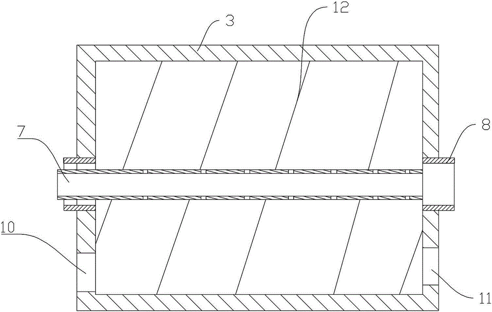
[0013] The reference signs in the drawings of the description include: base 1, support 2, roller 3, first motor 4, second motor 5, collecting roller 6, hot air pipe 7, rotating shaft 8, printing paper 9, inlet 10, outlet 11 , guide rib 12.

[0014] The embodiment is basically as attached figure 1 , figure 2 As shown: the top of the base 1 is provided with a bracket 2, the center of both ends of the roller 3 is fixedly connected with a rotating shaft 8, the roller 3 is installed on the bracket 2 through the rotating shaft 8, the first motor 4 is connected with the rotating shaft 8 at the right end of the roller 3, The rotating shaft 8 at the left end of the roller 3 is a hollow structure, the right end of the hot gas pipe 7 is a closed structure, and the hot gas pipe 7 extends into the roller 3 through the rotating shaft 8 of the hollow structure, so that the right end ...


PUM


Abstract

The application of the invention relates to the field of printing equipment, in particular to drying equipment used for drying printing paper printed. The printing paper drying equipment comprises a roller, wherein rotating shafts are fixedly connected in the centers of the two ends of the roller, the roller is mounted on a bracket through the rotating shafts, a first motor is connected with the rotating shaft at one end of the roller, the rotating shaft at the other end of the roller adopts a hollow structure, a hot gas pipe penetrates through the hollow structure and extends into the roller, and gas through holes are formed in the part, positioned in the roller, of the hot gas pipe; a guide rib is further arranged on the inner wall of the roller, and the roller is provided with an inlet at the beginning end of the guide rib and an outlet at the bottom end of the guide rib; and a collecting roller for collecting printing paper and a second motor for driving the collecting roller to rotate are further arranged on a base, and the collecting roller is positioned at the outlet part. The equipment greatly saves drying time, improves the drying efficiency, and meanwhile, also reduces land occupying area. The equipment can directly wrap dried printing paper well through the collecting roller, save the procedure of collecting again after air-drying and save time and labor.

Description

technical field [0001] The invention relates to the field of printing equipment, in particular to drying equipment for drying the printing paper after the printing paper is printed. Background technique [0002] Printing is a technology that transfers the ink to the surface of paper, fabric, plastic, leather and other materials through plate making, ink application, and pressurization to copy the contents of the original manuscript in batches. As the country of origin of printing, my country has deep research on printing technology. According to the different printing materials used, printing is divided into paper printing, white iron printing, plastic printing, textile printing, wood printing, glass printing, etc. . Among them, the paper products obtained by paper printing are printed with exquisite patterns such as flowers and English letters, which can be used for packaging. Various patterns can also be printed on them to form calligraphy and paintings for viewing. Differ...

Claims


Application Information

Patent Timeline
IPC IPC(8): F26B13/10B41F23/04
Inventor 胡佐林
Owner DINGSHENG CORP
Why Eureka
Eureka Blog
Learn More