X-Y axis linkage device and linkage method of 3D printer
A 3D printer and shaft linkage technology, applied in the direction of additive processing, etc., can solve the problems of high cost, low space utilization, poor printing quality, etc., achieve the effect of reducing equipment cost, compact equipment structure, and improving overall printing quality
- Summary
- Abstract
- Description
- Claims
- Application Information
AI Technical Summary
Problems solved by technology
Method used
Image
Examples
Embodiment 1
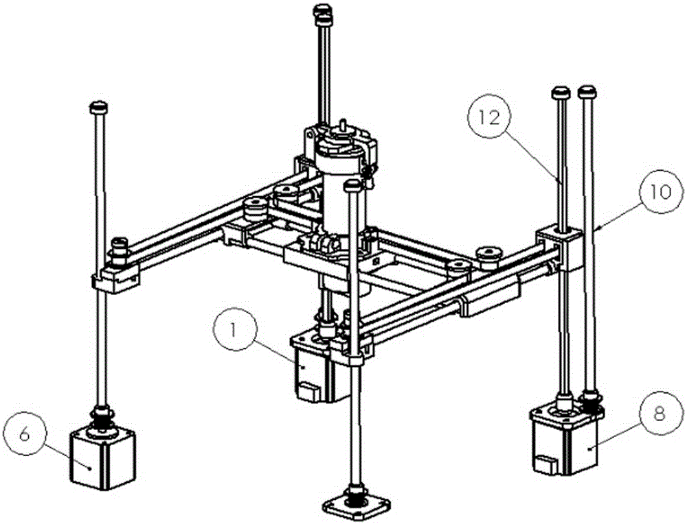
[0038] Such as Figure 4 As shown, the left and right motors move in the same direction at the same speed. For example, 1) when the left and right motors rotate clockwise at the same time, and the speed is the same, the print head moves along the negative direction of the X axis; 2) when the left and right motors rotate counterclockwise at the same time, and the speed is the same , the print head moves along the positive direction of the X axis.
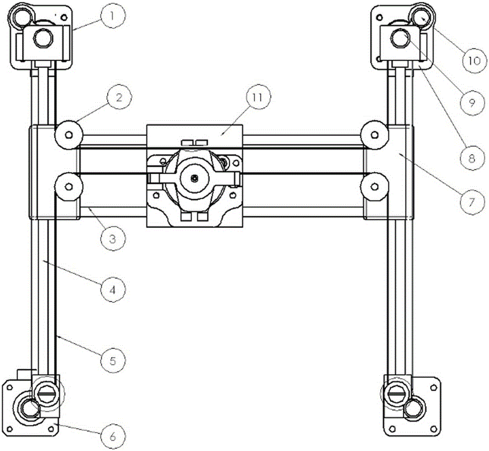
[0039] When the left and right motors move in the same direction and at the same speed, the synchronous belt 5 makes a circular motion, and the two auxiliary wheels 2 on the same side of the Y axis rotate in the opposite direction at a constant speed driven by the synchronous belt, so the X guide rod remains stationary in the Y direction; The two auxiliary wheels 2 on the same side of the X axis rotate at the same speed and in the same direction, so the print head moves in the X direction. Because the print head is associated with t...
Embodiment 2
[0041] Such as Figure 5 As shown, the left and right motors move in opposite directions at the same speed. For example, 3) when the left motor rotates counterclockwise and the right motor rotates clockwise, and the speeds are the same, the print head moves in the negative direction of the Y axis; 4) when the left motor rotates clockwise When it rotates clockwise and the right motor rotates counterclockwise, and the speed is the same, the print head moves forward along the Y axis.
[0042] When the left and right motors move in the opposite direction at the same speed, the two motors and the driven wheel respectively form a constant speed reverse circular motion. At this time, the auxiliary wheel does not rotate, the print head remains stationary in the X direction, and the X guide rod moves in the Y direction. Same with motor turning inside and out.
Embodiment 3
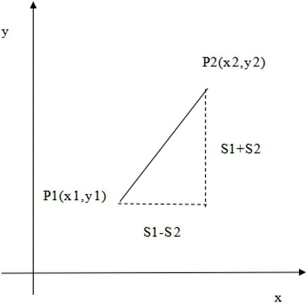
[0044] Such as Figure 6 As shown, the left and right motors rotate at different speeds. For example, 5) when the left motor rotates clockwise and the right motor stops rotating, the print head moves at 45° along the negative direction of the X axis and the positive direction of the Y axis; 6) when the left motor rotates When the right motor rotates counterclockwise and the right motor stops, the print head moves along the positive direction of the X axis and the negative direction of the Y axis at 45°; 7) When the right motor rotates clockwise and the left motor stops rotating, the print head moves along the negative direction of the X axis , Y-axis moves at 45° in the negative direction; 8) When the right motor rotates counterclockwise and the left motor stops rotating, the print head moves at 45° along the X-axis positive direction and the Y-axis positive direction; when the left motor and the right motor respectively When rotating in different directions and at different s...
PUM
 Abstract
Description
Claims
Application Information
 - R&D Engineer
- R&D Manager
- IP Professional
- Industry Leading Data Capabilities
- Powerful AI technology
- Patent DNA Extraction
Browse by: Latest US Patents, China's latest patents, Technical Efficacy Thesaurus, Application Domain, Technology Topic, Popular Technical Reports.
© 2024 PatSnap. All rights reserved.Legal|Privacy policy|Modern Slavery Act Transparency Statement|Sitemap|About US| Contact US: help@patsnap.com


