
Microstructure laser-induce implantation method and device based on turbid liquid target

A microstructure, laser-induced technology, applied in laser welding equipment, welding equipment, metal processing equipment, etc., can solve problems such as difficulty, easy consumption, and difficulty in guaranteeing, and achieve the effect of improving surface performance, increasing manufacturing efficiency, and improving efficiency.

Inactive Publication Date: 2016-01-06
GUANGDONG UNIV OF TECH
View PDF7 Cites 13 Cited by
  • Summary
  • Abstract
  • Description
  • Claims
  • Application Information

AI Technical Summary

Problems solved by technology

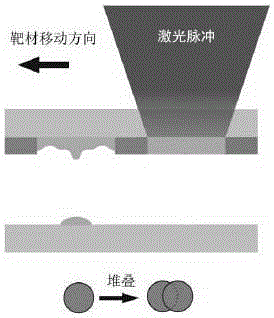
Due to the extremely thin target (about a few microns) and the extremely small gap between the target and the substrate (about tens of microns), it is very difficult to control the deposition of continuous microstructures by using laser-induced forward transfer stacking
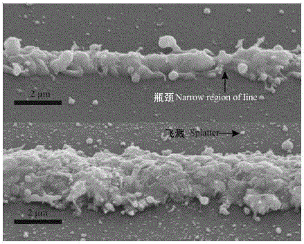
Moreover, the target material will be melted or even vaporized by the laser during the transfer process, and it is difficult to avoid problems such as spattering, resulting in major deficiencies in the uniformity of the microstructure and the quality of the morphology.
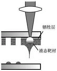
The existing "liquid target forward transfer technology" coats a liquid target layer of tens of microns on the transparent constrained layer, and uses laser energy to implant the target into the substrate. The "liquid target forward transfer technology" is due to The liquid target layer is still relatively thin (about tens of microns) and is easily consumed. In order to obtain a continuous microstructure with good quality, it is still difficult to select laser parameters and control the movement of the target.
In addition, after the liquid is dried, it is difficult to ensure the continuity and uniformity of the residual solids and the bonding strength between them and the substrate.

Method used


Image

  • Microstructure laser-induce implantation method and device based on turbid liquid target
  • Microstructure laser-induce implantation method and device based on turbid liquid target
  • Microstructure laser-induce implantation method and device based on turbid liquid target

Examples


Embodiment Construction

[0026] The following will clearly and completely describe the technical solutions in the embodiments of the present invention with reference to the accompanying drawings in the embodiments of the present invention. Obviously, the described embodiments are only some, not all, embodiments of the present invention. Based on the embodiments of the present invention, all other embodiments obtained by persons of ordinary skill in the art without creative efforts fall within the protection scope of the present invention.

[0027] see image 3 , a structural schematic diagram of a method for laser-induced implantation of microstructures based on a suspension target and a device for implementing the method provided by a preferred embodiment of the present invention.

[0028]In the laser-induced implantation method of microstructure based on the suspension liquid target in this embodiment, the laser 1 generates a high-energy pulsed laser 5 , and the energy and frequency of the laser are...


PUM


Abstract

The invention discloses a microstructure laser-induce implantation method based on a turbid liquid target. The method comprises the steps that a base material is placed in turbid liquid, containing fine particles, in glassware; laser light is focused on the position, wherein fine particles need to be implanted, of the base material through a convex lens after passing through a reflector; when focused laser energy is higher than the breakdown threshold value of liquid, laser breaks down the turbid liquid to cause plasma expansion and plasma shock waves radiate out; shock waves can radiate out when cavitation bubbles generated through induction after plasma disappears burst; high-speed microjet is generated through interaction between the cavitation bubbles and the surface of the base material; the generated shock waves and high-speed microjet push the fine particles to be implanted into the base material under impact. According to the method, laser energy does not directly act on the implanted target and can not damage the target, and the turbid liquid in any depth containing the fine particles is adopted to replenish the implanted target continuously, so that continuous microstructure preparation efficiency is improved. The invention further discloses a device using the method.

Description

technical field [0001] The invention relates to the technical field of surface microstructure processing, in particular to a method and device for laser-induced implantation of microstructures based on suspension liquid targets. Background technique [0002] Surface functionalization technology has been an important direction of scientific research for a long time, and its application in the field of engineering is becoming more and more common. In recent years, the development of micro-nano technology has injected new vitality into the research of surface functionalization, and has shown a broader application prospect. By changing the microscopic physical and chemical composition of the surface of the object, or processing a certain microstructure on the surface, the mechanical, corrosion, optoelectronic, friction and wear, and fluid mechanics characteristics of the working surface can be improved, thereby improving the working performance and efficiency of the device. [...

Claims


Application Information

Patent Timeline
IPC IPC(8): B23K26/352
Inventor 黄志刚印四华李洪辉杨青天郭钟宁杨洋
Owner GUANGDONG UNIV OF TECH
Learn More