Llc resonant power converter

A power converter and resonant technology, which is applied in the field of LLC resonant power converters, can solve problems such as increasing electromagnetic interference, affecting circuit stability, and circuit misoperation

Inactive Publication Date: 2015-12-30
WISTRON CORP
View PDF6 Cites 10 Cited by
  • Summary
  • Abstract
  • Description
  • Claims
  • Application Information

AI Technical Summary

Problems solved by technology

However, in order to increase the resonance frequency fs, the capacitance value of the resonance capacitor Cr is reduced, for example, to 15nF, when the input voltage Vdc is a high voltage, such as 367V, as Figure 4 As shown, the resonant frequency fs will be increased from 110.3KHz to 158.6KHz. At this time, it can be seen that although the conversion efficiency (output power 62.5W / input power 68.5W=91.24%) has improved, but because the circuit operating frequency is higher than 150KHz, so too much Excessive high-frequency operation will affect the stability of the circuit, easily lead to circuit misoperation, and increase the problem of electromagnetic interference (EMI)

Method used


Image

  • Llc resonant power converter
  • Llc resonant power converter
  • Llc resonant power converter

Examples


Embodiment Construction

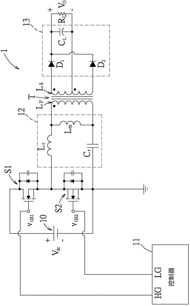
[0053] see Figure 5 Shown is the first preferred embodiment of the LLC resonant power converter of the present invention, which is used to convert an input voltage Vdc (for example, 126V-370V) from a DC voltage source 20 into a fixed output voltage Vo ( For example, 24V), wherein the input voltage Vdc may be within a first voltage range (eg, 126V-245V) or within a second voltage range (eg, 246V-370V) greater than the first voltage range. In addition, the LLC resonant power converter 2 of this embodiment includes a first power switch S1, a second power switch S2 connected in series with the first power switch S1, and a switch for controlling the conduction and switching of the first power switch S1 and the second power switch S2. No controller 21 , a transformer T, an LLC resonant circuit 22 arranged between the second power switch S2 and the transformer T, and a rectification and filtering circuit 23 .

[0054] The transformer T includes a primary winding Lp and a secondary ...


PUM


Abstract

A LLC resonant power converter for converting an input voltage from a direct current power source into an output voltage includes a first power switch, a second power switch, a transformer, a rectifying filter circuit, an LLC resonant circuit including a resonant inductor, a magnetizing inductor, and a variable capacitor that are electrically connected in series, a controller that controls the first power switch and the second power switch to be alternately switched to an on-state and that controls the variable capacitor to have a first capacitance value or a second capacitance value when the controller determines that the input voltage is within a first voltage range or a second voltage range, respectively.

Description

technical field [0001] The invention relates to a power conversion circuit, in particular to an LLC resonant power converter. Background technique [0002] see figure 1 As shown, an existing LLC resonant power converter 1 mainly includes a first power switch S1 and a second power switch S2 connected in series, both of which are electrically coupled to a DC power source 10 to receive an input voltage Vdc. And it is controlled by a controller 11 to switch conduction in turn. An LLC resonant circuit 12 is electrically coupled between the second power switch S2 and a primary winding Lp of a transformer T. As shown in FIG. Moreover, the secondary coil Ls of the transformer T is electrically coupled to a rectification filter circuit 12 for rectifying and filtering the voltage induced by the secondary coil Ls to provide an output voltage Vo. [0003] The LLC resonant circuit 12 is composed of a resonant capacitor Cr, a leakage inductance Lr of the primary coil Lp of the transfor...

Claims


Application Information

Patent Timeline
Patent Type & Authority Applications(China)
IPC IPC(8): H02M3/28H02M3/335
CPCY02B70/10H02M1/0022H02M1/0058H02M7/4818H02M3/33571H02M3/01
Inventor 林顺长李绍曾
Owner WISTRON CORP
Why Eureka
Try Eureka