
Rotary type compressor

A rotary compressor and compression mechanism technology, applied in the field of compressors, can solve the problems of separation of unfavorable oil-gas mixture, increase of oil discharge volume of compressor, etc., and achieve the effect of reducing loss, reducing oil volume and improving work efficiency

Active Publication Date: 2015-12-30
GUANGDONG MEIZHI COMPRESSOR +1
View PDF5 Cites 4 Cited by
  • Summary
  • Abstract
  • Description
  • Claims
  • Application Information

AI Technical Summary

Problems solved by technology

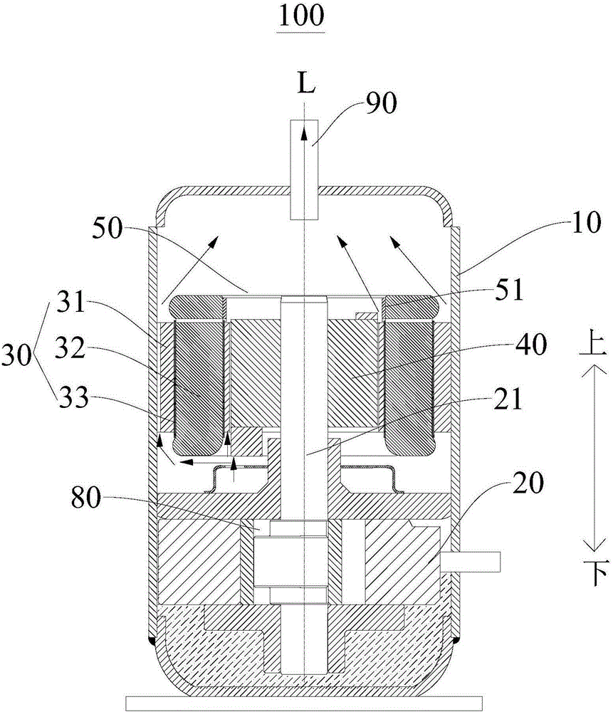
[0004] With the miniaturization and high frequency of the compressor, the internal structure is more compact, the distance between the motor part and the compression mechanism is further reduced, and the space in this area is also reduced. This factor is not conducive to the separation of the oil-air mixture, which will make the compressor The oil output is further increased

Method used


Image

  • Rotary type compressor
  • Rotary type compressor
  • Rotary type compressor

Examples


Embodiment Construction

[0038] Embodiments of the present invention are described in detail below, examples of which are shown in the drawings, wherein the same or similar reference numerals designate the same or similar elements or elements having the same or similar functions throughout. The embodiments described below by referring to the figures are exemplary only for explaining the present invention and should not be construed as limiting the present invention.

[0039] In describing the present invention, it should be understood that the terms "center", "longitudinal", "transverse", "length", "width", "thickness", "upper", "lower", "front", " Orientation indicated by rear, left, right, vertical, horizontal, top, bottom, inside, outside, clockwise, counterclockwise, etc. The positional relationship is based on the orientation or positional relationship shown in the drawings, which is only for the convenience of describing the present invention and simplifying the description, rather than indicati...


PUM


Abstract

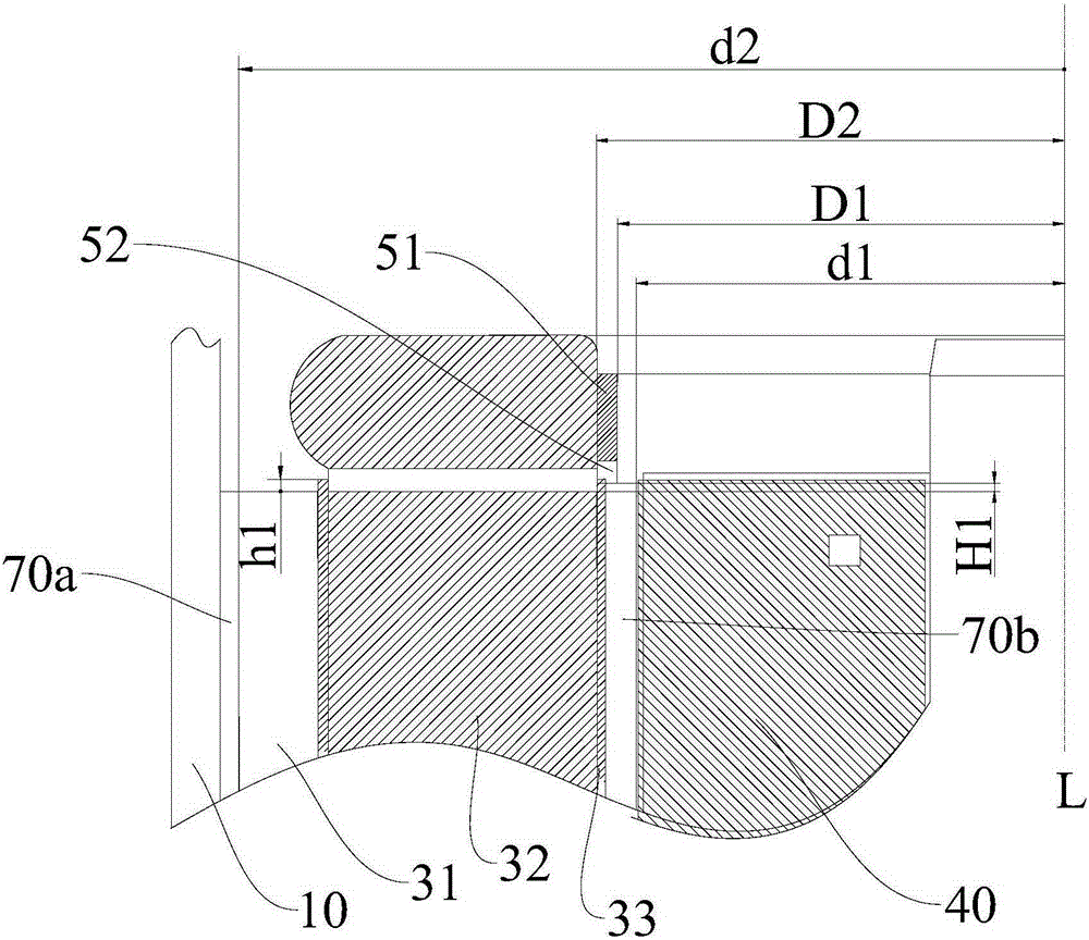
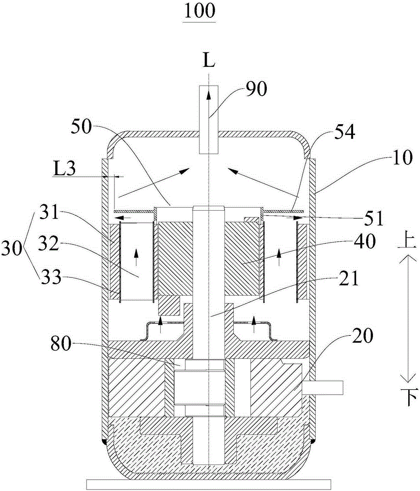
The invention discloses a rotary type compressor. The rotary type compressor comprises a shell, a compression mechanism which is arranged in the shell and possesses a crankshaft, a stator arranged above the compression mechanism, a rotor arranged in the stator, an oil separation device arranged at one side, far away from the compression mechanism, of the stator; the stator comprises a stator core and a stator coil reeling around the stator core; the crankshaft is arranged in the rotator and rotates under the driving effect of the rotator; and the oil separation device comprises a sleeve type main body, and the axis of the main body is coincident with the axis of the crankshaft. By arranging the oil separation device, lubricating oil is attached to the oil separation device, and the oil-spitting quantity of the rotary type compressor.

Description

technical field [0001] The invention relates to the technical field of compressors, in particular to a rotary compressor. Background technique [0002] In the related art, the rotary compressor includes a compression mechanism and a motor arranged in the casing. The motor includes a stator fixed on the casing and a rotor rotating inside the stator. The channel groove of the side cavity, the compression mechanism includes the cylinder, the crankshaft, the main bearing installed on the side of the cylinder close to the motor and inserted into the crankshaft, and the auxiliary bearing installed on the side of the cylinder away from the motor and inserted into the crankshaft, wherein the main bearing has a The valve channel is equipped with a muffler with an exhaust hole on the side of the main bearing away from the cylinder. The compression mechanism works under the drive of the rotor: the refrigerant enters the cylinder through the suction channel, and after being compressed ...

Claims


Application Information

Patent Timeline
IPC IPC(8): F04C23/02F04C29/00
Inventor 孟亮
Owner GUANGDONG MEIZHI COMPRESSOR
Learn More