
150mw ultra-high pressure extraction and condensing steam turbine

A 1.150MW, ultra-high pressure technology, applied in the direction of mechanical equipment, engine components, machines/engines, etc., can solve the problems of uncontrollable steam extraction, reduced unit working efficiency, energy loss, etc., to reduce energy loss and complete machine layout Compact and energy-saving effect

Active Publication Date: 2017-01-11
HARBIN TURBINE +1
View PDF5 Cites 0 Cited by
  • Summary
  • Abstract
  • Description
  • Claims
  • Application Information

AI Technical Summary

Problems solved by technology

[0003] The present invention aims to solve the problem that the existing 150MW steam turbine unit takes over the steam extraction from the steam extraction pipeline, and cannot control the steam extraction volume, resulting in energy loss and reduced working efficiency of the unit, and further provides a 150MW ultra-high pressure steam extraction and condensing steam turbine

Method used


Image

  • 150mw ultra-high pressure extraction and condensing steam turbine
  • 150mw ultra-high pressure extraction and condensing steam turbine
  • 150mw ultra-high pressure extraction and condensing steam turbine

Examples


specific Embodiment approach 1

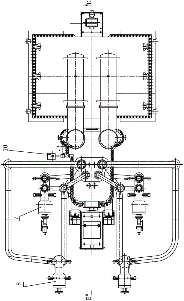
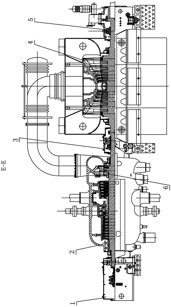
[0008] Specific implementation mode one: combine Figure 1-Figure 4 Explain that the 150MW ultra-high pressure steam extraction and condensing steam turbine in this embodiment includes a front bearing housing 1, an ultra-high pressure, medium and high pressure combined cylinder 2, a middle bearing housing 3, an ultra-high pressure and low pressure cylinder 4, a rear bearing housing 5, and a rotating partition 6. The slewing mechanism and the power mechanism 10; the ultra-high pressure, medium and high pressure combined cylinder 2 is connected between the front bearing housing 1 and the middle bearing housing 3, and the ultra-high pressure and low pressure cylinder 4 is connected between the middle bearing housing 3 and the rear bearing housing 5;

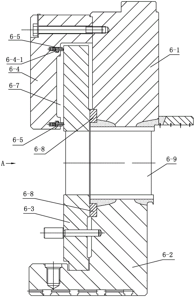
[0009] A rotating partition 6 is installed in the ultra-high pressure, medium and high pressure joint cylinder 2, and the rotating partition 6 includes the outer ring 6-1 of the board, the inner ring 6-2 of the board, the rotating ri...

specific Embodiment approach 2

[0012] Specific implementation mode two: combination Figure 4 Explain that the rotary mechanism of this embodiment includes a lever 9-2, a connecting rod 9-3 and a swing rod 9-4; the power mechanism 10 is an oil motor, and the oil motor is installed on the outer surface of the casing of the ultra-high pressure, medium and high pressure cylinder 2, The piston rod of the oil motor is rotationally connected to one end of the lever 9-2, the other end of the lever 9-2 is connected to one end of the connecting rod 9-3, and the other end of the lever 9-2 is rotationally and sealed installed in the ultra-high pressure, medium and high pressure joint cylinder 2 On the shell, the connecting rod 9-3 and the swing rod 9-4 are arranged in the ultra-high pressure, high and medium pressure joint cylinder 2, the other end of the connecting rod 9-3 is connected with the swing rod 9-4, and the swing rod 9-4 is connected with the connecting convex Shank 6-6 connection. In this way, there is a ...

specific Embodiment approach 3

[0013] Specific implementation mode three: combination image 3 Note that the outer ring 6-1 of the plate in this embodiment is an outer ring of a chromium-molybdenum alloy steel plate, and the inner ring 6-2 of the plate is an inner ring of a chromium-molybdenum steel plate. In this way, the chrome-molybdenum alloy steel is used, and the temperature resistance can reach 500°C, so it can operate safely at 400°C for a long time. Others are the same as in the first or second embodiment.


PUM


Abstract

The invention relates to a turbine, in particular to a 150MW ultrahigh pressure steam extraction and condensing type turbine, and aims to solve the problems that steam is extracted from a steam extraction pipeline connection pipe of a 150MW turbine unit and the extraction flow of steam cannot be controlled so that energy loss is caused, and the turbine unit efficiency is reduced. The turbine comprises a front bearing box, an ultrahigh pressure and high-intermediate pressure combined cylinder, a middle bearing box, an ultrahigh pressure and low pressure cylinder, a rear bearing box, a rotary baffle, a rotary mechanism and a power mechanism; the ultrahigh pressure and high-intermediate pressure combined cylinder is connected between the front bearing box and the middle bearing box, and the ultrahigh pressure and low pressure cylinder is connected between the middle bearing box and the rear bearing box; the rotary baffle is mounted in the ultrahigh pressure and high-intermediate pressure combined cylinder and comprises a plate body outer ring, a plate body inner ring, a rotary ring, a cover ring, an elastic sealing ring, a connection convex handle and a stationary blade; the rotary ring is arranged between the cover ring and the plate body outer ring, and the cover ring is connected with the plate body outer ring. The 150MW ultrahigh pressure steam extraction and condensing type turbine is used for heating power generation of combined heat and power generation.

Description

technical field [0001] The invention relates to a steam turbine, in particular to a 150MW ultra-high pressure industrial steam extraction and condensing steam turbine. Background technique [0002] The parameters of the domestic industrial steam extraction 150MW steam turbine unit currently in operation are mainly to take over the extraction steam from the steam extraction pipeline, and the extraction steam volume cannot be controlled, resulting in energy loss and reducing the working efficiency of the unit. Contents of the invention [0003] The present invention aims to solve the problem that the existing 150MW steam turbine unit takes over steam extraction from the steam extraction pipeline, cannot control the steam extraction volume, causes energy loss, and reduces the working efficiency of the unit, and further provides a 150MW ultra-high pressure steam extraction and condensing steam turbine. [0004] The technical scheme adopted by the present invention to solve the...

Claims


Application Information

Patent Timeline
Patent Type & Authority Patents(China)
IPC IPC(8): F01D17/10F01D17/26F01D25/16
Inventor 张秋鸿党丽丽付强赵英英郑兰琴张月红刘顺华李佳佳曲滨荣刘丹
Owner HARBIN TURBINE
Learn More