Partially-enhanced X-cor foam core sandwich T-joint structure and molding method
A technology of local reinforcement and molding method, applied in the field of fiber composite material reinforcement, can solve the problems of strength and complicated process, and achieve the effects of improving production efficiency, improving connection performance and high production efficiency
- Summary
- Abstract
- Description
- Claims
- Application Information
AI Technical Summary
Problems solved by technology
Method used
Image
Examples
Embodiment 1
[0033] Example 1: Combining Figure 1-2 This embodiment will be described.
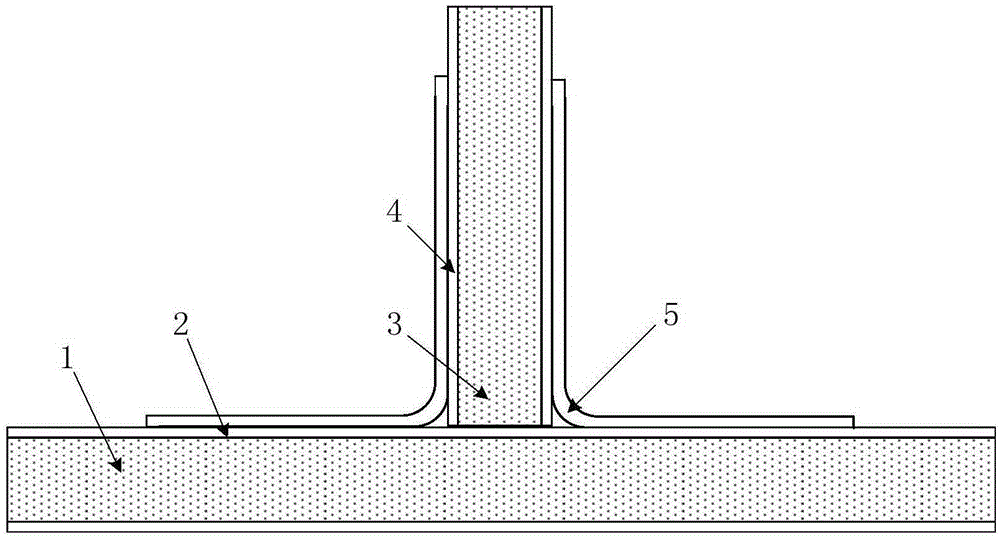
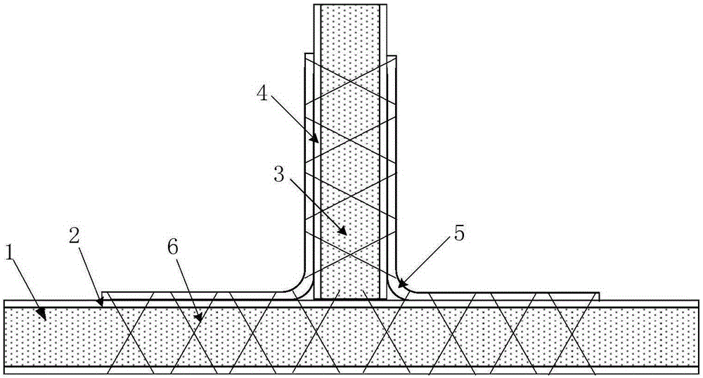
[0034] A locally reinforced X-cor foam sandwich T-joint structure (such as figure 2 ) includes skin foam core material 1, skin panel 2 wrapped outside it; web foam core material 3, web panel 4 wrapped outside it, skin foam core material 1 and web foam core material 3 perpendicular The connection forms a T-shaped joint, and the two sides of the T-shaped joint are fixed by the reinforcing layer 5. By implanting high-performance Z-pin6 inside the foam core material, it is possible to implant Z-pin6 in the weak performance of the T-shaped joint, that is, the connection area. Supporting the foam core material can also improve the connection performance of the T-joint. The reinforcing layer 5 has an L-shaped structure, one end is connected to the skin panel 2 and the other end is connected to the web panel 4 .
[0035] Such as figure 1 It is a schematic cross-sectional view of a foam sandwich T-shaped ...
Embodiment 2
[0036] Example 2: Combining Figure 1-4 This embodiment will be described.
[0037] A method for forming a partially reinforced X-cor foam sandwich T-joint, comprising the following steps:
[0038] Step 1: Using T300 carbon fiber (3K tow) and FW125 epoxy resin as raw materials, prepare high-performance fully cured Z-pin6 with a diameter of 0.5mm through advanced pultrusion equipment;
[0039] Step 2: On the skin foam core material 1 and the web foam core material 3 (PMI, Rohacell-51WF, thickness 12.5mm), mark out the area where the T-joint needs to be implanted with the Z-pin, and place the Z-pin according to the following Set the parameters (the angle is 60°, the spacing is 5mm×5mm), implant the high-strength foam core material, and expose the corresponding lengths at both ends of the foam in different areas, and the skin core material exposed part length a, b (such as image 3 , a=b=1.5mm) corresponds to the thickness of the skin panel 2 plus the reinforcing layer, (the th...
PUM
 Abstract
Description
Claims
Application Information
 - R&D
- Intellectual Property
- Life Sciences
- Materials
- Tech Scout
- Unparalleled Data Quality
- Higher Quality Content
- 60% Fewer Hallucinations
Browse by: Latest US Patents, China's latest patents, Technical Efficacy Thesaurus, Application Domain, Technology Topic, Popular Technical Reports.
© 2025 PatSnap. All rights reserved.Legal|Privacy policy|Modern Slavery Act Transparency Statement|Sitemap|About US| Contact US: help@patsnap.com


