Display panel, preparation method of display panel, display device and health monitoring method of display device
A technology for a display panel and a display device, which is applied in the directions of measurement device, identification device, gain control, etc., can solve the problems such as inconvenience of thinning development of display device and affecting the production efficiency of display device, etc.
- Summary
- Abstract
- Description
- Claims
- Application Information
AI Technical Summary
Problems solved by technology
Method used
Image
Examples
Embodiment 1
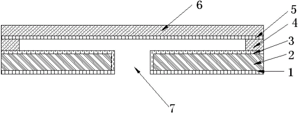
[0078] The display panel provided by the embodiment of the present invention has a thin film transistor 10, and the thin film transistor 10 has a top gate structure. Its structure includes: an active layer 13, a gate insulating layer 12 arranged on the active layer 13, a gate layer 11 arranged on the gate insulating layer 12, and an interlayer formed on the gate layer 11, formed on the Source 15 and drain 14 on the spacer.
[0079] Such as figure 2 As shown, the thin film transistor 10 in the display panel provided by this embodiment includes a gate layer 11, a gate insulating layer 12, a polysilicon active layer, and a source and drain electrode layer. The thin film transistor 10 is located on the shielding metal layer on the base substrate. , And is electrically isolated from the shielding metal layer by the insulating layer;
[0080] The first electrode layer 21 of the acoustic wave sensor and the shielding metal layer are arranged in the same layer;
[0081] The silicon backpl...
Embodiment 2
[0092] Such as image 3 As shown, the display panel provided in this embodiment has a thin film transistor 10, which has a bottom gate structure, and its structure specifically includes a gate layer 11, a gate insulating layer 12 disposed on the gate layer 11, and The active layer 13 on the gate insulating layer 12 and the source 15 and the drain 14 provided on the active layer 13. Specifically, the thin film transistor includes a gate layer 11, a gate insulating layer 12, an amorphous silicon active layer, and a source and drain electrode layer. The first electrode layer 21 of the acoustic wave sensor and the gate layer of the thin film transistor 11 Same layer settings;
[0093] The silicon backplate 22 of the acoustic wave sensor is arranged in the same layer as the amorphous silicon active layer in the thin film transistor; the second electrode layer 26 of the acoustic wave sensor is arranged in the same layer as the source and drain electrode layers of the thin film transist...
Embodiment 1
[0114] The method provided in this embodiment is directed to the manufacturing method of the display panel provided in the above embodiment 1. Such as Figure 4 As shown, the specific preparation steps include:
[0115] Step 001: forming a first through hole at a fixed position of a glass substrate;
[0116] Step 002, forming a buffer layer on the glass substrate;
[0117] Step 003, forming a first electrode layer on the buffer layer;
[0118] Specifically, the first electrode layer includes a plurality of metal strip electrodes arranged at intervals.
[0119] Step 004: A silicon nitride layer is formed on the first electrode layer;
[0120] Specifically, the silicon nitride layer serves as the active layer on the thin film transistor and the silicon backplane of the acoustic wave sensor.
[0121] Step 005, forming a gate insulating layer on the silicon nitride layer;
[0122] Specifically, the gate insulating layer serves as the electret of the acoustic wave sensor at the same time, and ...
PUM
 Abstract
Description
Claims
Application Information
 - R&D
- Intellectual Property
- Life Sciences
- Materials
- Tech Scout
- Unparalleled Data Quality
- Higher Quality Content
- 60% Fewer Hallucinations
Browse by: Latest US Patents, China's latest patents, Technical Efficacy Thesaurus, Application Domain, Technology Topic, Popular Technical Reports.
© 2025 PatSnap. All rights reserved.Legal|Privacy policy|Modern Slavery Act Transparency Statement|Sitemap|About US| Contact US: help@patsnap.com


