
A method of dynamic matching and dynamic correction

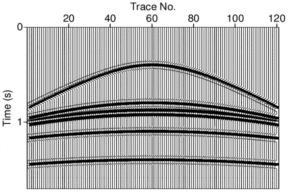
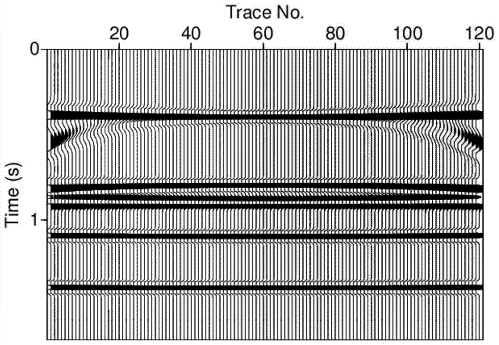
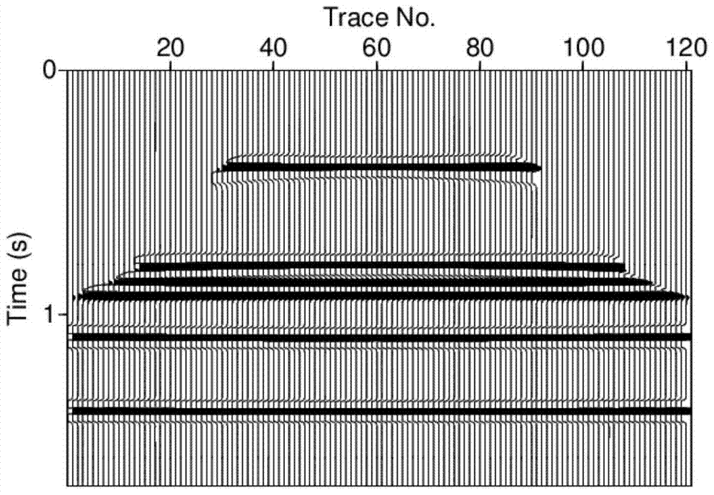
A dynamic matching and dynamic correction technology, applied in the field of seismic exploration, can solve the problems of inaccurate focus of velocity spectrum energy values, reduced velocity picking accuracy, inaccuracy, etc., to eliminate wavelet stretching effect, improve stacking effect and velocity inversion effect

Active Publication Date: 2018-01-02
BC P INC CHINA NAT PETROLEUM CORP +1
View PDF5 Cites 0 Cited by
  • Summary
  • Abstract
  • Description
  • Claims
  • Application Information

AI Technical Summary

Problems solved by technology

The commonly used velocity spectrum picking method often has inaccurate and inaccurate focus of the velocity spectrum energy value, which reduces the accuracy of velocity picking

Method used


Image

  • A method of dynamic matching and dynamic correction
  • A method of dynamic matching and dynamic correction
  • A method of dynamic matching and dynamic correction

Examples


Embodiment Construction

[0026] First of all, before describing the embodiments of the present application, it is necessary to introduce a dynamic time correction method (DTW), which can be used for seismic signals f(i) and g( i) Calculate its time error u(0:N-1), the formula used is:

[0027] |u[i]-u[i-1]|≤1

[0028] |u[i]|≤L

[0029] i=0,1,...N-1; (3)

[0030] Among them, u(0:N-1) represents an optimal solution of time-matching moveout, and N is the length of seismic signals f(i) and g(i).

[0031] When u[i]-u[i-1]=1, two adjacent points in f(i) correspond to two non-adjacent points in g(i). When u[i]-u[i-1]=-1, two adjacent points in f(i) correspond to one point in g(i). Because two similar seismic waves do not change very sharply, the limitation of formula (3) has practical geological significance. The process carried out in the steps of this application is all carried out under the restriction of formula (3).

[0032] The technical means adopted by the present invention to achieve the inten...


PUM


Abstract

The invention discloses a dynamic matching and dynamic correction method, comprising: acquiring the original seismic data of a CMP or CIP seismic trace with M seismic traces and each trace having N sampling points, selecting a zero offset seismic trace; calculating and obtaining the trace Direction forward error, trace direction reverse error; carry out the trace direction smoothing process, calculate and obtain the trace direction smoothing error of M seismic traces; regard the trace direction smoothing error as a new one with M seismic traces and each trace has N The seismic data of the sampling points are transposed and processed to calculate the direction smoothing error of the sampling point; the direction smoothing error of the sampling point is regarded as a seismic data and transposed to obtain the positive error in the direction of the original seismic data after smoothing; in the reverse direction Calculate the time difference between the zero-offset seismic trace of the original seismic data and each of the M seismic traces according to the principle of minimum value tracing, and use the time difference to correct the time difference of all traces in the original seismic data to obtain the time difference field. This time difference field is subjected to motion correction processing.

Description

technical field [0001] The invention relates to the technical field of seismic exploration, in particular to a dynamic matching and dynamic correction method. Background technique [0002] In seismic data processing, motion correction technology is a very common method. Initially, the conventional motion correction was based on the hyperbolic time distance equation (Dix, 1955), and it was performed point by point. However, at large offsets, the seismic wave time distance Curves are not hyperbolic. Afterwards, Taner and Koehler (1969) used the first three terms of Taylor series expansion to make a fourth-order correction of normal jet lag, which improved the accuracy of the approximate formula. Tsvankin and Thomsen (1994) gave a long-offset dynamic correction formula for horizontal single-layer anisotropic media. Conventional dynamic correction with a large offset will cause serious stretching of the wavelet. Usually, we directly cut off the severely stretched area and fill...

Claims


Application Information

Patent Timeline
Patent Type & Authority Patents(China)
IPC IPC(8): G01V1/36
Inventor 陈双全靳松李向阳
Owner BC P INC CHINA NAT PETROLEUM CORP
Learn More