Steel band tape scale error measuring method
A technology of scale error and measurement method, applied in the direction of bendable ruler, etc., can solve the problems of low accuracy, reading error, large labor load, etc., and achieve the effect of improving measurement accuracy, ensuring accuracy, and reducing the amount of calculation.
- Summary
- Abstract
- Description
- Claims
- Application Information
AI Technical Summary
Problems solved by technology
Method used
Image
Examples
Embodiment 1
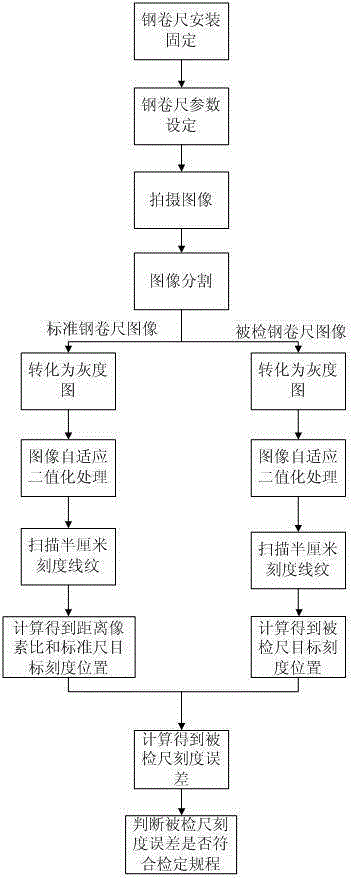
[0039] like figure 1 As shown, the method for measuring the scale error of the steel tape includes the following steps: Step 1, install and fix the inspected ruler and the standard ruler horizontally and horizontally on the verification platform; Step 2, use the camera to take pictures at the measuring point to obtain the image of the steel tape; Step 3 1. Process the steel tape image to obtain the distance pixel ratio b of the standard ruler; step 4, obtain the target scale position W1 of the standard ruler and the target scale position W2 of the inspected ruler; step 5, use the obtained standard ruler target scale position W1, Calculate the scale error of the inspected ruler from the target scale position W2 of the inspected ruler and the distance pixel ratio b, and determine whether the scale error at the measuring point of the inspected ruler meets the requirements.
[0040]In step 1 of this embodiment, both the inspected ruler and the standard ruler installed and fixed ar...
Embodiment 2
[0045] The difference between this embodiment and Embodiment 1 is that the way of obtaining the target scale position W1 of the standard ruler and the target scale position W2 of the inspected ruler is different. The specific method of obtaining the target scale position W1 of the standard ruler and the target scale position W2 of the inspected ruler in this implementation is as follows : In this embodiment, when obtaining the target scale position W1 of the standard ruler, the target scale line pattern of the standard steel tape is manually selected in the collected steel tape image, and the framed image is intercepted from the steel tape image to perform image grayscale and binary Value processing, and then horizontally scan the position of the scale line in the intercepted image (there is only one scale line in the intercepted image, the position of the target scale line can be easily obtained), and the target scale line position W1 of the standard ruler is the target scale l...
Embodiment 3
[0047] This embodiment makes the following further limitations on the basis of Embodiment 1 or Embodiment 2: This embodiment also includes manually selecting any target scale line pattern of the inspected ruler in the collected steel tape image, and the frame selection image from The steel tape is intercepted from the image for image grayscale and binarization, and the scale lines are scanned horizontally in the intercepted image to obtain the starting point and end point of the target scale line pixels of the inspected scale (the target scale line is white, and the horizontal direction is from the left. Scan to the right, from black to white is the starting point, from white to black is the end point) to get the pixel difference of the target scale line of the inspected ruler (end position - starting position), and according to the target scale line pixel of the inspected ruler The difference value and the distance pixel ratio of the standard ruler are used to calculate the ta...
PUM
 Abstract
Description
Claims
Application Information
 - R&D
- Intellectual Property
- Life Sciences
- Materials
- Tech Scout
- Unparalleled Data Quality
- Higher Quality Content
- 60% Fewer Hallucinations
Browse by: Latest US Patents, China's latest patents, Technical Efficacy Thesaurus, Application Domain, Technology Topic, Popular Technical Reports.
© 2025 PatSnap. All rights reserved.Legal|Privacy policy|Modern Slavery Act Transparency Statement|Sitemap|About US| Contact US: help@patsnap.com

