


Quick Research
Generate reliable direction feasibility study reports for your R&D in just a few steps.

Technical Q&A
Discover and master advanced knowledge NOW. Basics, ideas, possibilities, all at once.

Find Solutions
As an expert in R&D theories, this can generate solutions to your technical problems instantly.

Evaluate Feasibility
Analyze your overall solution with one click, know your potential R&D risks in advance.

Monitor Landscape
Get weekly tech updates, stay abreast of the latest tech innovations and key insights.
Yarn joint bonding device and bonding method
A technology of bonding device and yarn, which is applied in the directions of transportation and packaging, transportation of filamentous materials, and processing of thin materials, etc., can solve the problems of incomplete cohesion, incomplete entanglement of end fibers into the yarn body, and easy end breakage. Achieve the effect of improving efficiency, realizing automatic operation and improving quality
- Summary
- Abstract
- Description
- Claims
- Application Information
AI Technical Summary
Problems solved by technology
Method used
Image

Examples
Embodiment 1
[0032] This embodiment provides a yarn joint bonding device.
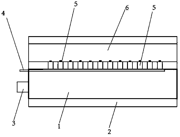
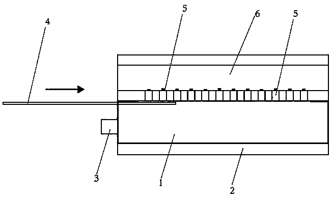
[0033] A yarn splice bonding device, see figure 1 and figure 2 As shown, it includes a stocker 1, a heating and heat preservation part 2, a material extrusion part 3, a switch part, a positioning part and an induction part. The positioning part has a positioning groove 6 for the yarn to pass through, and the material extrusion part 3 is connected to the storage container 1, the sensing part is connected to the switch part, and the sensing part is an inductor; the switch part is a movable partition 4, and the movable partition 4 is slidably connected to the storage The feeder 1 is used to open or close the second opening. When the movable partition 4 is closed, see figure 1 shown; when the movable partition 4 is opened, see figure 2 shown.
[0034] The positioning component is connected to the stocker 1, and the positioning component has a plurality of channels 5, and the openings at both ends of the channel ...
Embodiment 2
[0040] This embodiment provides a method for using the yarn joint bonding device.
[0041] A method for using a yarn joint bonding device, comprising the steps of:
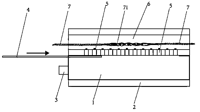
[0042] see image 3 As shown, the yarn is placed in the positioning groove 6 of the positioning part, the yarn advances at a certain speed, and when the yarn is not broken without jointing, the material extruding part 3 and the movable partition 4 are in the initial position;
[0043]When the sensing part receives the yarn knotting action signal, the switch part is turned on, and the multiple channels 5 on the positioning part are opened, the material extruding part 3 squeezes the stocker 1, and the hot melt adhesive in the stocker 1 passes through The channel 5 enters the yarn in the positioning groove 6, and the hot melt glue is sprayed onto the yarn joint and then cross-linked at normal temperature to make the yarn joint bonded, and the high temperature and sizing process in the subsequent dyeing and sizing pr...
Embodiment 3
[0051] This embodiment provides a method for using the yarn joint bonding device.
[0052] see image 3 As shown, in this embodiment, the second opening area of the channel 5 on the positioning groove 6 in the yarn joint bonding device is 3mm 2 The distance between each adjacent channel 5 is 5 mm. When the yarn is not broken and does not need to be knotted, the heating and insulating part 2 outside the stocker 1 is heated and kept warm at a temperature of 100 ° C.
[0053] After the yarn breaks, the automatic knotting of the winding machine triggers the movable partition 4 in the yarn joint bonding device to be pulled out upwards, the channel 5 is opened, the positioning groove 6 determines the position of the joint, and the material extrusion part 3 starts to work at the same time. Through the channel 5, the hot melt adhesive is evenly distributed on the joints of the yarns, and the hot melt adhesive is quickly cross-linked at room temperature, so that the bonding between ...
PUM
 Abstract
Description
Claims
Application Information
 - R&D Engineer
- R&D Manager
- IP Professional
- Industry Leading Data Capabilities
- Powerful AI technology
- Patent DNA Extraction
Browse by: Latest US Patents, China's latest patents, Technical Efficacy Thesaurus, Application Domain, Technology Topic, Popular Technical Reports.
© 2024 PatSnap. All rights reserved.Legal|Privacy policy|Modern Slavery Act Transparency Statement|Sitemap|About US| Contact US: help@patsnap.com