
Automatic cable transfer system

A technology of automatic transmission and cable transmission, which is applied in the directions of cable laying equipment, transportation and packaging, and delivery of filamentous materials, etc. problems, to achieve the effect of reducing the use of cranes and labor, broad practical and market prospects, and reducing manpower input

Active Publication Date: 2018-03-20
博锋智能科技(大连)有限公司
View PDF15 Cites 0 Cited by
  • Summary
  • Abstract
  • Description
  • Claims
  • Application Information

AI Technical Summary

Problems solved by technology

[0007] The present invention solves the problems that the whole process of cable laying cannot be fully automated, time-consuming, labor-intensive, low in laying efficiency, and high in cost. The space for cable laying is narrow, the cable conveyor cannot be used, a large amount of manpower is required, and the synchronization of different stations, Speed ​​control, stroke control, direction adjustment, the change of the outer diameter of the cable cannot be adapted at any time, the problem of constant data collection and unified control, the cable reel is placed on the cable rack with a crane or a jack, a lot of manpower is required when the cable is pulled, and the cable reel cannot Stop at any time, the rotation direction and speed of the cable reel, the balance of the cable rack under inertia, and the constant control of the cable laying process, provide an automatic cable transmission system

Method used


Image

  • Automatic cable transfer system
  • Automatic cable transfer system
  • Automatic cable transfer system

Examples


Embodiment Construction

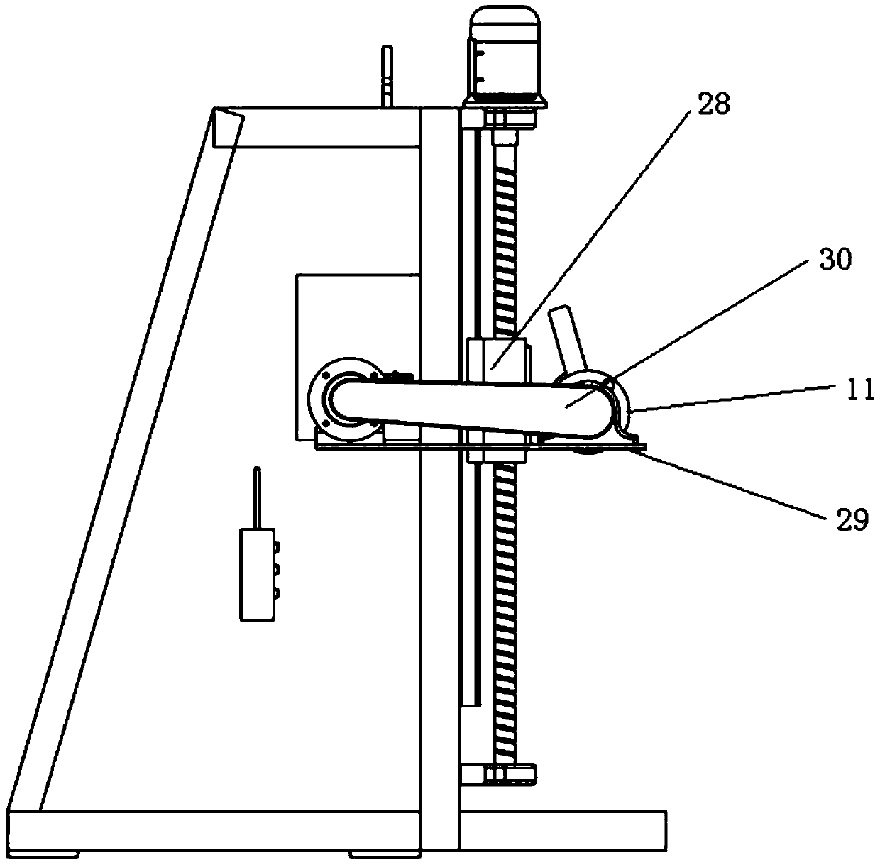
[0033] Such as figure 1As shown, the automatic cable transmission system includes a general controller, a cable reel 1, an automatic portable cable transmission robot 4, a metal wire sheath 5, a steel wire rope 6, a synchronous positioning traction device 7, an automatic cable lifting and laying device 8 and a bracket 9 A cable reel 1 is installed on the automatic cable lifting and laying device 8, a bracket 9 is placed on the side of the automatic cable lifting and laying device 8, and several automatic portable cable transmission robots 4 and a synchronous positioning traction device 7 are fixed on the bracket 9 in turn. , a cable roller 3 is arranged between two adjacent automatic portable cable transmission robots 4, and the cable roller 3 is fixed on the bracket 9. When two adjacent automatic portable cable transmission robots 4 are far away, the cable 2 is transmitted on the cable roller 3, which avoids the cable 2 being dragged on the bracket 9 and cannot be moved. The ...


PUM


Abstract

The invention discloses an automatic cable transmission system, which includes a general controller, a cable reel, an automatic portable cable transmission robot, a metal rope sheath, a steel wire rope, a synchronous positioning traction device, a cable automatic lifting and laying device and a bracket, and the cable is automatically lifted and lowered. A cable reel is installed on the laying device, and a bracket is placed on the side of the automatic cable lifting and laying device, and several automatic portable cable transmission robots and a synchronous positioning traction device are fixed on the bracket in turn. There is a pay-off metal rope cover connected to the top, and the pay-off metal rope cover is connected with the cable wound on the cable reel. The cable automatic lifting and laying device, the automatic portable cable transmission robot, and the synchronous positioning traction device are respectively connected with the master controller. The invention realizes the fully automatic operation of the whole cable laying process, saves time and effort, has extremely high laying efficiency and low cost.

Description

technical field [0001] The invention relates to the technical field of electromechanical equipment, in particular to an automatic cable transmission system. Background technique [0002] At present, the whole process of cable laying cannot be fully automated, which is time-consuming and laborious, with low laying efficiency and high cost. [0003] In the process of cable laying, especially in the field of ship and offshore construction, the site environment is narrow and the distribution of cable trays is relatively complicated (usually cable trays with a specific height and width). Traditional cable conveyors cannot be used and cannot meet the actual working conditions. In the whole process, manual pulling is used to lay the cables along the predetermined path, which incurs huge labor costs and requires the cooperation of special operators. [0004] On-site multi-work and cross-operation is common, and the environment is relatively noisy. During the manual pulling process,...

Claims


Application Information

Patent Timeline
Patent Type & Authority Patents(China)
IPC IPC(8): B65H49/34B65H49/36H02G1/06
Inventor 周博周海锋杨政叶爱学
Owner 博锋智能科技(大连)有限公司
Learn More