A telescope lens barrel milling processing fixture

A technology of milling processing and telescope, applied in the direction of manufacturing tools, metal processing equipment, metal processing machinery parts, etc., can solve the problems of difficult to guarantee the size of the processing position, unable to automatically adjust the center, low work efficiency, etc., to meet the needs of convenient processing and improve The effect of high-speed turning processing quality and convenient operation

Inactive Publication Date: 2017-06-13
YUNNAN TENGDA MACHINERY MFG CO LTD +1
View PDF5 Cites 0 Cited by
  • Summary
  • Abstract
  • Description
  • Claims
  • Application Information

AI Technical Summary

Problems solved by technology

[0002] like figure 1 As shown, the outer side of the telescope lens barrel is an irregular curved surface, and the hole C on the curved surface needs to be milled, but the traditional processing fixture can only clamp and process one part at a time, the work efficiency is low, and it cannot be automatically centered, clamped, and positioned. The operation is inconvenient, and the size of the processing position is difficult to guarantee

Method used


Image

  • A telescope lens barrel milling processing fixture
  • A telescope lens barrel milling processing fixture
  • A telescope lens barrel milling processing fixture

Examples


Embodiment Construction

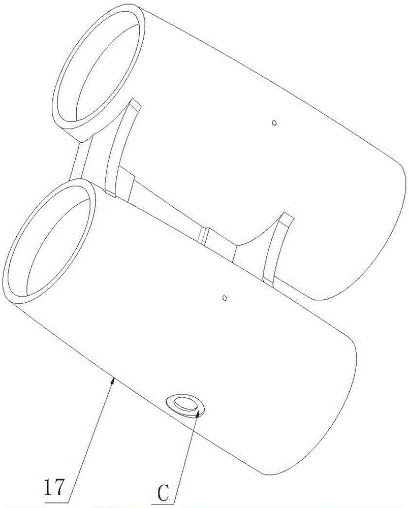
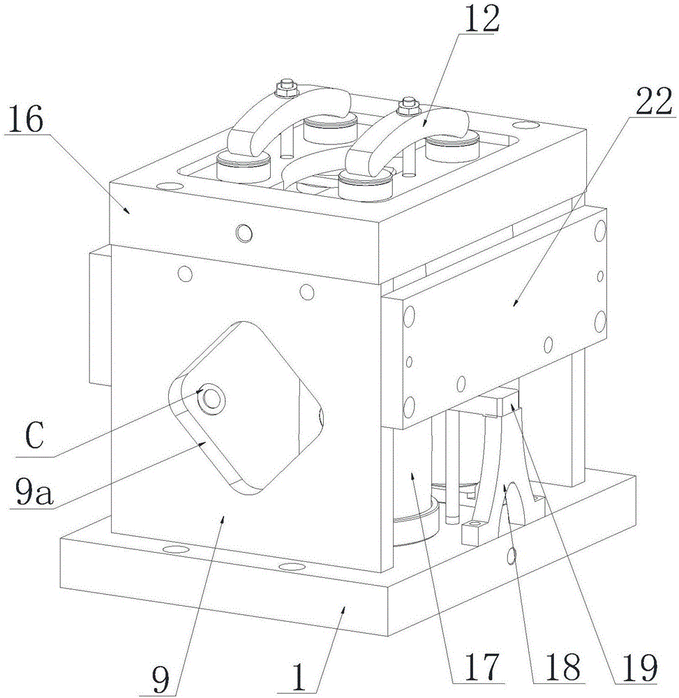
[0013] Such as Figure 1 to Figure 5 Shown: the present invention mainly is made up of clamping body, positioning device, clamping device. The present invention can clamp two pairs of telescope lens barrels at one time. The clamp body is surrounded by the bottom plate 1, the left side plate and the right side plate 9, the cover plate 16, the front side top plate and the rear side top plate 22, and a rhombus hole 9a is opened in the center of the left side plate and the right side plate 9, The diamond-shaped hole is facing the position of the hole C to be milled on the outer curved surface of the telescope lens barrel. Side plates of different shapes and opening forms can also be used, as long as they can meet the supporting function of the side plates of the clamp body and ensure the exposure of the processing position to facilitate the processing of the machine tool. Described positioning device is divided into the big end positioning device and the small end positioning de...


PUM


Abstract

A milling clamp for telescope lens barrels comprises a clamp body, a positioning device and a clamping device. The clamp body is formed by a bottom plate, a left side plate, a right side plate, a cover plate, a front side top plate and a rear side top plate in an enclosed mode. The center of the left side plate and the center of the right side plate are each provided with a hole. The positioning device comprises large end positioning device bodies and small end positioning device bodies which are arranged on the two telescope lens barrels symmetrically. A first part of the clamping device comprises inverted-Y-shaped supports symmetrically arranged in the middles of the front side and the rear side of the bottom plate, long threaded rods located at the inner sides of the inverted-Y-shaped supports and pressing blocks which are pressed on the inverted-Y-shaped supports, and the inner end and the outer end of each pressing block are installed on the corresponding long threaded rods in a sleeving mode. A second part of the clamping device comprises a main rod, an adjusting threaded rod, middle pressing blocks and a main adjusting nut, wherein the main rod is vertically installed in the center of the bottom plate, and the top of the main rod is provided with an inner threaded hole; the adjusting threaded rod is installed in the inner threaded hole in the top end of the main rod in a matched mode; the middle pressing blocks are sequentially installed on the adjusting threaded rod in a sleeving mode; the top end of the adjusting threaded rod is inserted in the cover plate. By means of the clamp, position control and accuracy control over outer machining surfaces of the telescope lens barrels can be achieved rapidly and accurately.

Description

technical field [0001] The invention relates to the technical field of milling fixtures for side parts of telescope lens barrels. Background technique [0002] Such as figure 1 As shown, the outer side of the telescope lens barrel is an irregular curved surface, and the hole C on the curved surface needs to be milled, but the traditional processing fixture can only clamp and process one part at a time, the work efficiency is low, and it cannot be automatically centered, clamped, and positioned. The operation is inconvenient, and the size of the processing position is difficult to guarantee. Contents of the invention [0003] The object of the present invention is to solve the problems of the prior art, and provide a telescope barrel milling fixture with reasonable structure, convenient operation, and fast and accurate control of the position and precision of the outer processing surface of the telescope barrel. [0004] The purpose of the present invention is achieved th...

Claims


Application Information

Patent Timeline
Patent Type & Authority Patents(China)
IPC IPC(8): B23Q3/06
CPCB23Q3/061B23Q3/062B23Q3/069
Inventor 徐连江杨艳春张武
Owner YUNNAN TENGDA MACHINERY MFG CO LTD
Why Eureka
Try Eureka