Pipe end facing machine

A flat head machine and pipe technology, applied in metal processing and other directions, can solve the problems of slow feeding speed, inability to cooperate with pipe production lines, low processing efficiency, etc., to achieve the effect of improving processing efficiency, avoiding material transfer process and simple structure

Active Publication Date: 2015-12-23
张家港市中悦冶金设备科技有限公司
View PDF7 Cites 3 Cited by
  • Summary
  • Abstract
  • Description
  • Claims
  • Application Information

AI Technical Summary

Problems solved by technology

[0002] The existing pipe flat head equipment mostly uses manual feeding, as described in the patent: a new type of pipe flat head machine (patent number ZL201120032174.8), this kind of equipment has slow feeding speed, low processing efficiency, and cannot be combined with the pipe production line With the use of

Method used


Image

  • Pipe end facing machine
  • Pipe end facing machine
  • Pipe end facing machine

Examples


Embodiment Construction

[0023] Specific embodiments of the present invention will be described in detail below in conjunction with the accompanying drawings.

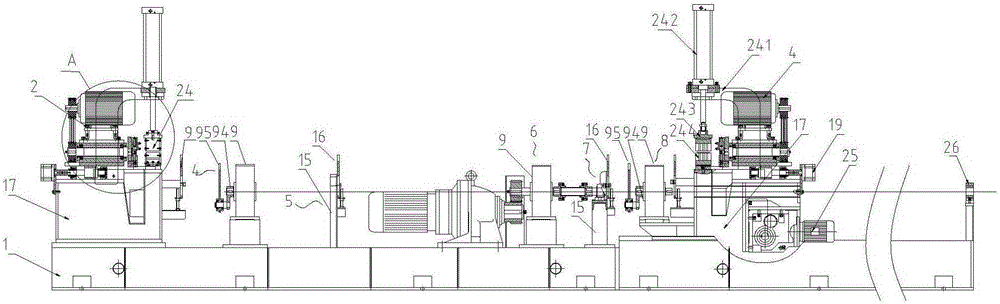
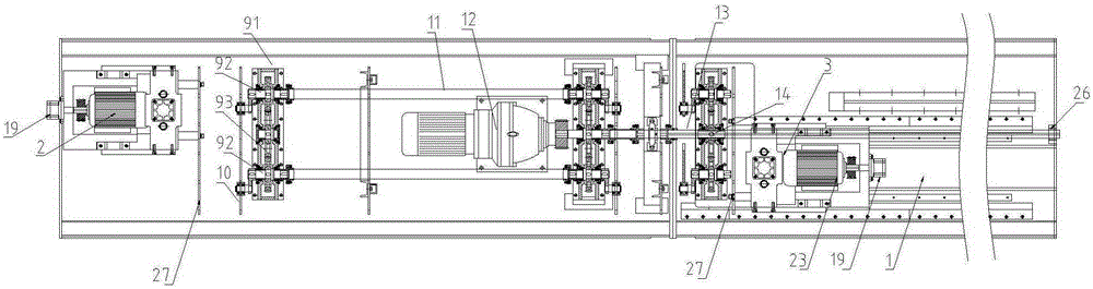
[0024] Such as Figure 1-4 As shown, a pipe flat head machine includes a machine platform 1, the left end of the machine platform 1 is fixedly provided with a left flat head device 2, the right end of the machine platform 1 is provided with a right flat head device 3 that can slide left and right, and the left flat head device 2 is installed on the machine platform 1. A feeding device is arranged between the right flat head device 3.

[0025] The feeding device includes a left feeding mechanism 4, a left supporting mechanism 5, a middle feeding mechanism 6, a right supporting mechanism 7, and a right feeding mechanism 8, which are sequentially arranged on the machine platform 1 from left to right;

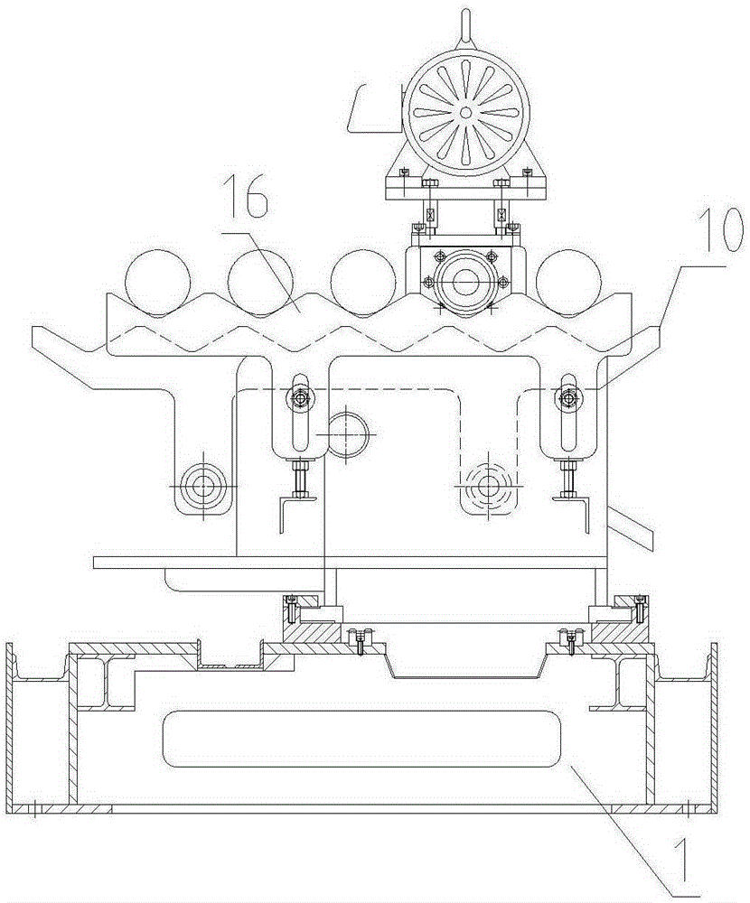
[0026] Left and right feeding mechanism 8 all comprise gear box 9 and the feeding plate 10 that is movably arranged on the left side of gear box ...


PUM


Abstract

The invention discloses a pipe end facing machine. The pipe end facing machine comprises a machine station, wherein a left end facing device is fixed at the left end of the machine station; a right end facing device capable of sliding leftwards and rightwards is arranged at the right end of the machine station; a feeding device for radially conveying pipes is arranged between the left end facing device and the right end facing device on the machine station. The pipe end facing machine can load materials automatically and can cooperate with a pipe production line for use.

Description

technical field [0001] The invention relates to a pipe processing equipment, in particular to a pipe flattening machine. Background technique [0002] The existing pipe flat head equipment mostly uses manual feeding, as described in the patent: a new type of pipe flat head machine (patent number ZL201120032174.8), this kind of equipment has slow feeding speed, low processing efficiency, and cannot be combined with the pipe production line With the use of. Contents of the invention [0003] The technical problem to be solved by the present invention is to provide an automatic feeding pipe flattening machine which can be used in conjunction with the pipe production line. [0004] In order to solve the above-mentioned technical problems, the technical solution adopted in the present invention is: a pipe flat head machine, including a machine table, a left flat head device is fixed at the left end of the machine table, and a right flat head device that can slide left and righ...

Claims


Application Information

Patent Timeline
Patent Type & Authority Applications(China)
IPC IPC(8): B23D79/02B23Q7/00
Inventor 刘红光赵立群蒋龙
Owner 张家港市中悦冶金设备科技有限公司
Why Eureka
Try Eureka