
A method for calibrating the magnification of the miniature objective lens of direct-writing lithography machine

A calibration method and lithography machine technology, applied in the direction of microlithography exposure equipment, optics, optical components, etc., can solve the problems of difficult projection optical path magnification and large calibration error, and achieve the effect of easy implementation and high calibration accuracy

Active Publication Date: 2017-11-14
HEFEI CHIP FOUND MICROELECTRONICS EQUIP CO LTD
View PDF5 Cites 0 Cited by
  • Summary
  • Abstract
  • Description
  • Claims
  • Application Information

AI Technical Summary

Problems solved by technology

[0005] The purpose of the present invention is to provide a method for calibrating the magnification of the miniature objective lens of the direct-writing lithography machine, so as to solve the problems that the magnification of the projection optical path of the direct-writing lithography machine is difficult to calibrate and the error is too large

Method used


Image

  • A method for calibrating the magnification of the miniature objective lens of direct-writing lithography machine
  • A method for calibrating the magnification of the miniature objective lens of direct-writing lithography machine
  • A method for calibrating the magnification of the miniature objective lens of direct-writing lithography machine

Examples


Embodiment Construction

[0035] The present invention will be further described below in conjunction with the accompanying drawings and specific embodiments.

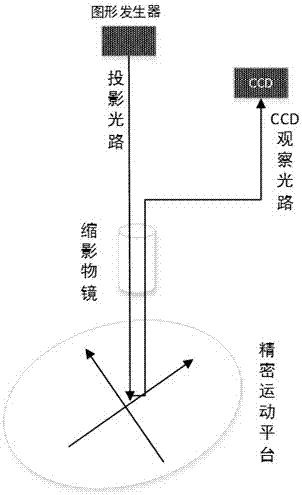
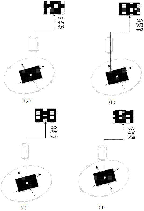
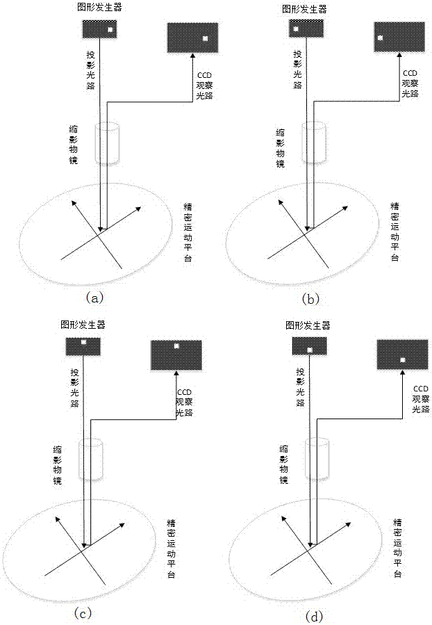
[0036] like Figure 1 ~ Figure 4 As shown, a method for calibrating the magnification of the miniature objective lens of a direct-writing lithography machine comprises the following steps:

[0037] S1. Select a mask plate (Mask1) with a marking pattern (Mark1) and place it on the base installed on the precision motion platform, and keep it fixed.

[0038] S2. Make sure that the marked figure (Mark1) can be observed from the CCD field of view.

[0039] S3. The precision motion platform is moved along the X-axis and Y-axis respectively for a fixed distance to ensure that the moved mark figure (Mark1) is still within the field of view of the CCD.

[0040] S4. For the mark pattern (Mark1) in the field of view of the CCD, the moving distance is captured by machine vision, and the mark pattern (Mark1) on the substrate can be calculated through the ...


PUM


Abstract

The invention provides a method for calibrating the magnification of the miniature objective lens of a direct-writing lithography machine, which includes: separately calculating the magnification of the CCD observation optical path from the mark pattern on the substrate through the miniature objective lens to the CCD along the X-axis and Y-axis directions of the precision motion platform ; respectively calculate the magnification of the entire optical path of the pattern generator through the miniature objective lens to the substrate and then from the substrate to the CCD along the X-axis and Y-axis directions of the precision motion platform; The magnification of a projection light path along the X-axis and Y-axis directions of the precision motion platform. The invention solves the problem of magnification calibration of the direct-writing lithography machine for the projection optical path from the pattern generator to the precision motion platform, and uses a specific optical structure to obtain the actual miniature magnification through the specific positional relationship between the CCD camera, the pattern generator and the precision motion platform, It is easy to implement and has high calibration accuracy.

Description

technical field [0001] The invention relates to the technical field of exposure of a direct-writing photolithography machine, in particular to a method for calibrating the magnification of a miniature objective lens of a direct-writing photolithography machine. Background technique [0002] Photolithography is used to print a pattern of features on the surface of a substrate. Such substrates may include chips used in the fabrication of semiconductor devices, various integrated circuits, flat panel displays (eg, liquid crystal displays), circuit boards, biochips, micromechanical electronic chips, optoelectronic circuit chips, and the like. [0003] In the direct writing exposure process, the substrate is placed on the substrate table of the precision motion platform, and the feature pattern is projected to the specified position on the substrate surface through the movement of the exposure device and the precision motion platform in the lithography equipment. In order to achi...

Claims


Application Information

Patent Timeline
Patent Type & Authority Patents(China)
IPC IPC(8): G02B13/00G02B7/00G01M11/02G03F7/20
Inventor 陆敏婷
Owner HEFEI CHIP FOUND MICROELECTRONICS EQUIP CO LTD
Learn More