Eureka AIR delivers breakthrough ideas for toughest innovation challenges, trusted by R&D personnel around the world.

Indoor positioning method and system for dynamic target

A dynamic target and indoor positioning technology, applied in the field of electronic information, can solve problems such as high cost, high hardware requirements, and easy to be affected by the environment, and achieve the effect of low cost, simple positioning method, and environmental universality

Inactive Publication Date: 2015-12-16
NO 63921 UNIT OF PLA
View PDF11 Cites 8 Cited by
  • Summary
  • Abstract
  • Description
  • Claims
  • Application Information

AI Technical Summary

Problems solved by technology

[0004] The RSSI positioning method uses the attribute of signal strength attenuation with distance to measure the target position. It has relatively low hardware requirements and low cost, but it is easily affected by the environment, and its accuracy and reliability are poor.
The TDOA positioning method converts signal propagation time into distance, is not affected by environmental conditions, and has high precision, but requires precise time synchronization of each base station, which requires very high hardware requirements and high cost
[0005] At present, the ranging carriers used in indoor positioning mainly include ultrasonic wave, pseudolite, wireless network and RFID (Radio Frequency Identification, radio frequency identification). The network and RFID mainly use the signal strength method. Although the positioning accuracy is not as good as the TDOA method, the cost is low. Especially since the rapid development of the "Internet of Things" in this century, the application of RFID has been greatly promoted. RFID-based technology has become a research hotspot for indoor positioning.

Method used


Image

  • Indoor positioning method and system for dynamic target
  • Indoor positioning method and system for dynamic target
  • Indoor positioning method and system for dynamic target

Examples


Embodiment Construction

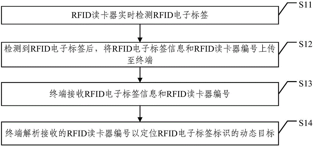
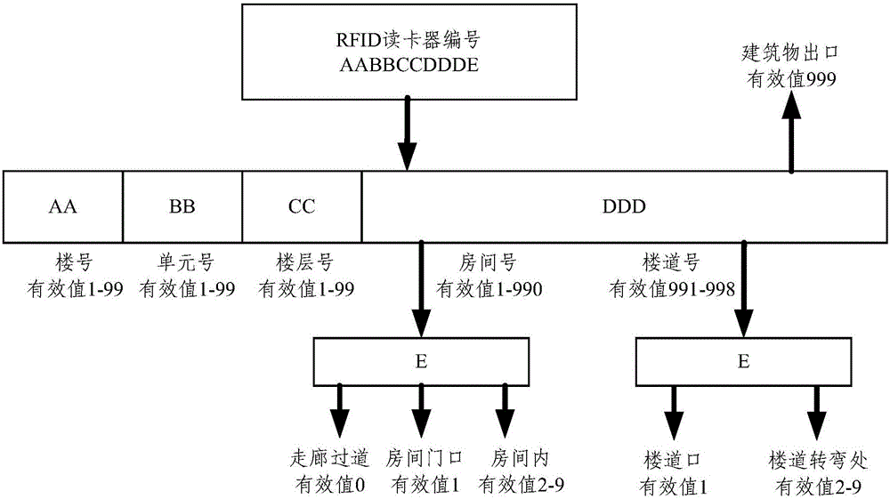
[0043] The embodiment of the present invention provides a dynamic target indoor positioning method and system, the main idea of ​​which is to install a radio frequency identification (RFID) electronic tag for each dynamic target to identify different dynamic targets. There are multiple indoor deployments of dynamic target activities. Radio frequency identification RFID card reader, wherein each RFID card reader has a unique number, which identifies the specific location of the RFID card reader in the room. When a dynamic target enters the range of a certain RFID card reader during the movement, the RFID card reader reads the information of the electronic tag corresponding to the dynamic target, and then sends it to the terminal together with the RFID card reader's own number, and the terminal reads the information based on the RFID The card number is analyzed to obtain the position of the RFID card reader, that is, to determine the position of the dynamic target identified by t...


PUM


Abstract

The embodiment of the invention discloses an indoor positioning method and a system for a dynamic target and applies to the field of electronic information technology, which solves the problem in the prior art that a dynamic target in an indoor environment (such as an office building) is high in positioning cost and poor in applicability. According to the technical scheme of the invention, an indoor positioning solution of low cost, strong adaptability and good environmental universality is provided to meet accuracy requirements. The method comprises the steps of arranging a plurality of radio-frequency identification (RFID) card readers indoors, wherein each RFID card reader is provided with a unique identification number; arranging an RFID electronic tag on each indoor dynamic target; on the condition that the RFID electronic tag is detected by one RFID card reader, uploading the number of the RFID card reader and the information of the detected RFID electronic tag to a terminal; receiving the number of the RFID card reader and the information of the detected RFID electronic tag by the terminal; and parsing the number of the RFID card reader to position a dynamic target identified by the RFID electronic tag.

Description

technical field [0001] The invention relates to the technical field of electronic information, in particular to a dynamic target indoor positioning method and system. Background technique [0002] Indoor positioning technology mainly uses technologies such as wireless communication, base station and satellite navigation to realize the location of indoor people or objects, which is convenient for monitoring the location of indoor people or objects. [0003] At present, indoor positioning technology mainly uses sound waves or radio signals emitted by multiple base stations with known precise positions for ranging, and three-dimensional positioning is realized through the intersection of ranging spherical surfaces. According to different ranging principles, indoor positioning methods can be divided into two types: RSSI (Radio Signal Strength Information, signal strength) and TDOA (Time Difference of Arrival, time difference of arrival). [0004] The RSSI positioning method use...

Claims


Application Information

Patent Timeline
IPC IPC(8): G01S1/02
CPCG01S1/02
Inventor 李强齐巍李作虎刘旭东罗海英李锋刘广军
Owner NO 63921 UNIT OF PLA
Why Eureka
Eureka Blog
Learn More